


16
Proprietary Information: Not for use or disclosure except by written agreement with Calix.
© Calix. All Rights Reserved.
Preparations Before You Begin
Complete the following preparations before you begin the installation process.
Site requirements
Before starting the installation, verify that the following conditions are true:
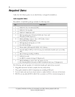
All materials are onsite and inventoried.
An equipment rack and grounding system are available
Minimum clearances are met for each device.
Access to a -48 VDC power source with fuse-protected distribution is available.
The installation site has restricted access.
Cable lengths and wire gauges are adequate for the services provided.
Thermal budget is accounted for and approved.
Assignments for power, transport, services, alarms, timing, and other interfaces have
been defined.
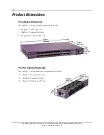
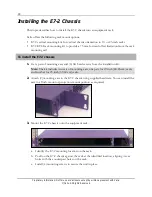
Determining an installation location
For indoor rack-mounted units, keep the following requirements in mind when choosing an
installation location:
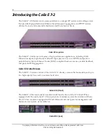
As an environmentally hardened system, the Calix E7-2 is suitable for installation in
network telecommunication facilities including outside plant (OSP) locations.
The E7-2 requires one rack unit (1 RU) of mounting space on a standard 19- or 23-inch
(48.26- or 58.42-cm) equipment rack.
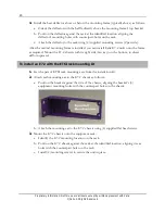
The E7-2 fan module is located on the right side of the unit. The system requires
adequate airflow space on the right side (intake) and left side (exhaust) of the unit for
proper cooling. For this reason, EIA or 23-inch (58.42-cm) racks are preferred over 19-
inch (48.26-cm) telco racks.
Note
: Calix offers an optional cool air intake and rear heat exhaust system to assure
adequate airflow. Refer to
Installing an Intake/Exhaust System
(on page
31
) for installation
instructions.
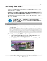
Locate the E7-2 near power supply and ground termination locations.
Note:
The power and ground cables supplied with the E7-2 installation kit are 12 feet
(3.66 meters) long.
Power, ground, and alarm wiring at the rear of the E7-2 must be properly secured with
strain relief.
Fibers attached to pluggable transceiver modules on the front of the E7-2 unit must be
appropriately dressed and secured with strain relief to avoid exceeding the manufacturer's
bend radius standards.
Содержание E7-2
Страница 1: ...Calix E7 2 Installation Guide May 2013 220 00320 Rev 13...
Страница 2: ......


