


39
Proprietary Information: Not for use or disclosure except by written agreement with Calix.
© Calix. All Rights Reserved.
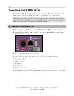
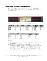
Wiring the BITS Timing Interface
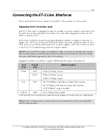
The E7-2 supports synchronization with an external clock source via timing inputs located
on the E7-2 rear panel. The E7-2 accepts a standard DSX-level timing source (DS1/T1
format only, not 64 kbps composite clock format) and should be set to ESF/B8ZS. Wire the
E7-2 timing inputs to a Building Integrated Timing System (BITS) clock source using
shielded cable.
Calix recommends providing traceable clock synchronization for E7-2 GPON applications.
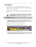
IN (A)
SHLD
TIP+
RNG-
IN (B)
SHLD
TIP+
RNG-
TIP+
RNG-
TIP+
RNG-
OUT (A)
OUT (B)
You can link up to ten collocated E7-2 shelves to share a BITS timing input. Calix offers a
connectorized daisy-chain BITS cable, or you can wire-wrap the individual daisy-chain links
between shelves.
To wire the BITS timing input interface
1.
Get up to two 24 AWG shielded 2-wire cables of sufficient length to reach the local
BITS clock interface from the E7-2. Use one cable to provide a single timing input (A
only), or two cables for a redundant input (A + B).
2.
Strip approximately one inch (2.54 cm) of insulation from the wire ends.
3.
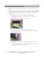
Wire the E7-2 external timing input(s) as follows:
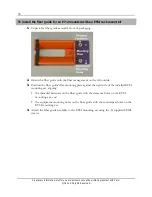
a.
Connect the timing wires to the E7-2 BITS
IN (A)
input position:
Wrap the positive (tip) wire to the
TIP+
pin.
Wrap the negative (ring) wire to the
RNG-
pin.
Wrap the cable shielding to the
SHLD
pin.
b.
To provide a redundant connection to the BITS clock source, repeat Step 3a to wire
the E7-2 BITS
IN (B)
input position, as required.
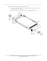
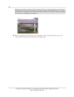
4.
Route and dress the timing input cable to the local BITS clock interface and connect per
local practice.
Содержание E7-2
Страница 1: ...Calix E7 2 Installation Guide May 2013 220 00320 Rev 13...
Страница 2: ......


