


14
Proprietary Information: Not for use or disclosure except by written agreement with Calix.
© Calix. All Rights Reserved.
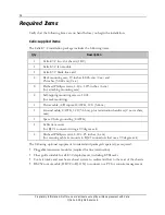
Required Items
Verify that the following items are on hand before you begin the installation.
Calix-supplied items
The Calix E7-2 installation package includes the following items:
Qty
Description
1
Calix E7-2 two-slot chassis (1 RU)
1
Calix E7-2 fan module
1
Calix E7-2 blank line card
4
Rack mounting ears; 19-inches (48.26-cm) (2 ea.) and
23-inches (58.42-cm) (2 ea.)
8
Flathead Phillips screws, 4-40 x .1875 inches (.6 cm)
(for attaching mounting ears)
4
Self-tapping mounting screws, 12-24
(for rack mounting)
1
Power cable, A/B inputs;18 AWG, 12 ft (3.66 m)
1
Ground cable; 8 AWG, 12 ft (3.66 m), plus termination hardware (2 ea. washers,
nuts)
1
Spare 2-hole ground lug (8 AWG)
4
Cable tie mounts
(for RJ-21 connector using a 90 degree exit)
4
Panhead Phillips screws, 4-40 x .25 inches (.6 cm)
(for securing cable tie mounts to RJ-21 connectors that use a 90 degree exit)
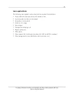
The following optional equipment is ordered and packaged separately, as required:
Pluggable transceiver modules (required for line termination)
Fiber guide suitable for all E7-2 deployments, including ETSI racks
Cool air intake and rear heat exhaust system to redirect airflow to the rear of the chassis
RS-232 console cable (DB-9F to RJ-11M) to connect to a PC for console management
Содержание E7-2
Страница 1: ...Calix E7 2 Installation Guide May 2013 220 00320 Rev 13...
Страница 2: ......


