


23
Proprietary Information: Not for use or disclosure except by written agreement with Calix.
© Calix. All Rights Reserved.
Connecting DC Power
The Calix E7-2 requires -48 VDC input power. The installation kit includes a 12-foot (3.66-
meter) DC power cable with A and B leads.
Note:
The E7-2 must be installed in an Isolated DC return (DC-I) configuration, where the
DC return is not connected to the grounding system.
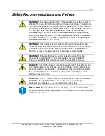
DANGER!
Risk of electric shock. Only a qualified technician should
perform this procedure
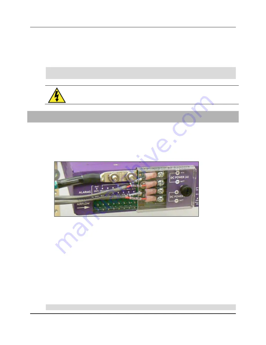
To connect DC power to the E7-2
1.
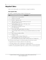
Get the DC power cable from the installation kit.
2.
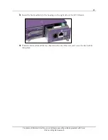
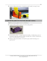
On E7-2 rear panel, loosen the captive thumbscrew securing the clear plastic power
terminal cover to the chassis, and then remove the cover.
3.
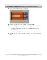
Connect the DC power cable to the E7-2 chassis as follows:
a.
Connect to the A-side power input:
Connect the black
(A)
RTN
wire to the
(A)
+
RTN
terminal.
Connect the red
(A) BATT
wire to the
(A) -
BATT
terminal.
b.
Connect to the B-side power input:
Connect the black
(B)
RTN
wire to the
(B)
+
RTN
terminal.
Connect the red
(B) BATT
wire to the
(B) -
BATT
terminal.
c.
Tighten the power termination screws to 9 in-lbs.
4.
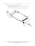
Replace the terminal cover and tighten the thumbscrew. Make sure all wires exit cleanly
to the left.
5.
Route the power cable to the local DC power source and connect it per local practice.
Note:
Use 7.5 Amp GMT fuses to protect the E7-2 DC distribution circuits.
Содержание E7-2
Страница 1: ...Calix E7 2 Installation Guide May 2013 220 00320 Rev 13...
Страница 2: ......


