


43
Proprietary Information: Not for use or disclosure except by written agreement with Calix.
© Calix. All Rights Reserved.
Connecting Fibers
Once the E7-2 line card sockets are equipped with pluggable transceiver modules, you can
connect fibers/cables to the ports as described below. Be sure the fiber connector type
matches the connector type of the module(s). Use LC connectors for Ethernet interfaces and
SC/UPC connectors for GPON interfaces.
If the laser at the far end of the fibers is enabled, you can use an optical power meter to test
signal strength before connecting fibers to the equipment. Defer to local practice wherever
applicable.
DANGER! CLASS 1 LASER PRODUCT. INVISIBLE LASER RADIATION
MAY BE PRESENT.
Fiber optic radiation can cause severe eye damage or
blindness. Do not look into the open end of an optical fiber.
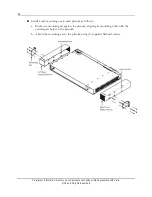
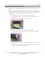
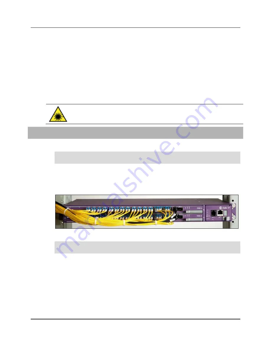
To connect fibers to the E7-2
1.
Route fibers (or copper Ethernet cables) to the E7-2 shelf, approaching from left side.
Important:
Route fibers to the left side of the E7-2 shelf to ensure visibility of system
and card status LEDs located on the right side of the E7-2 shelf.
2.
Remove the caps or plugs from the fiber connector ends, if present.
3.
Connect fibers to transceiver modules on the E7-2 line card.
4.
Repeat the steps above to connect additional fiber links, as required.
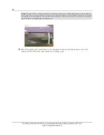
5.
Neatly dress and secure all fibers/cables per local practice.
Note:
To avoid pinching or interference with the equipment, neatly coil or bundle any
slack fiber and dress it toward the left side of the E7-2 shelf.
Содержание E7-2
Страница 1: ...Calix E7 2 Installation Guide May 2013 220 00320 Rev 13...
Страница 2: ......


