background image

29

GasAlertQuattro

European Performance Approval

Oxygen deficient atmospheres (<10% v/v) may suppress some 
sensor outputs.

Daily bump test: 

To comply with performance requirements for 

European certification, a bump test must be completed before 
each day’s use.

Calibration: 

To minimize measuring errors, the ambient 

conditions of temperature, humidity, and pressure during 
calibration should be as close as possible to the actual 
environmental conditions in which the instrument is intended to 
be used. 

Calibration interval: 

If the detector is to be used in 

atmospheres which may contain compounds known to interfere 
with, inhibit, or poison the sensors, the calibration intervals 
must be specified to take into account the possibility of a rapid 
loss in measurement sensitivity.


See page 7, 

Sensor Poisons 

and Contaminants

.

Sensor impairment

: Some types and concentrations of dust in 

the monitored atmosphere may impair the measuring function 
of the gas detector. Cross-sensitivities described in the sensor 
manufacturer’s data sheet must be considered.

Response time verification: 

Before use, confirm that the gas 

detector’s response time is fast enough to trigger alarms so that 
unsafe situations are avoided. If necessary, set the alarm levels 
below the standard safety-related limit values to allow enough 
time for protective measures to be carried out.

Instrument configuration: 

FleetManager II version 2.6.0 (or 

higher) must be used to make configuration changes to the 
GasAlertQuattro.

To conform with configuration requirements for European gas 
performance:

• Latching alarms must be enabled. 

See page 16

.

• Stealth mode must be disabled. 

See page 17

.

• Force Bump must be enabled. 

See page 12

.

• Bump Interval (days) must be set to 1 for all sensors. 
• IntelliFlash must be enabled. 

See page 17

.

• LEL Low Alarm and High Alarm values cannot be 0.

When detectors are configured using FleetManager II, BW 
strongly recommends that detector settings are reviewed prior 
to operation to ensure that they have been applied successfully 
and comply with performance requirements.

a

 CAUTION

Do not use for gas detection while connected to a PC.

Special conditions for safe use - oxygen measurement
Performance approval:

 The EC type examination certificate 

applies to the measurement of oxygen up to 25% (v/v).

Baseline and span zone blanking:

 Please note that oxygen 

measurements in the range from 20.5% (v/v) up to 21.3% (v/v) 
are indicated as “20.9%” oxygen on the instrument display. 
Measurement values in the range within ±0.2% (v/v) of the span 
gas concentration are displayed as the span gas concentration. 
For example, if the span gas concentration (used for oxygen 
bump testing) is configured as 18% (v/v), measured values in 

Содержание GasAlertQuattro 1

Страница 1: ...Quick Reference Guide 1 2 3 and 4 Gas Detector ...

Страница 2: ...the buyer promptly notifying BW of any defect and if required promptly making the product available for correction No goods shall be returned to BW until receipt by the buyer of shipping instructions from BW and c the right of BW to require that the buyer provide proof of purchase such as the original invoice bill of sale or packing slip to establish that the product is within the warranty period ...

Страница 3: ...6 Device Configuration 16 Sensor Configuration 18 Maintenance 19 Rechargeable Battery Capacity 19 Battery Pack Retaining Screw 19 Replacing the Battery Pack 20 Charging the Rechargeable Battery Pack 20 Replacing the Alkaline Batteries 21 WEEE Directive and Battery Directive 23 Removal and Disposal of the Coin Cell 23 Replacing the Sensors 24 Replacing the Sensor Filter 25 Specifications 26 Europea...

Страница 4: ......

Страница 5: ...UTION Warning Substitution of components may impair Intrinsic Safety Before using the detector refer to Sensor Poisons and Contaminants on page 8 Protect the combustible sensor from exposure to lead compounds silicones and chlorinated hydrocarbons Although certain organic vapors such as leaded gasoline and halogenated hydrocarbons may temporarily inhibit sensor performance in most cases the sensor...

Страница 6: ... recommends to bump test the sensors before each day s use to confirm their ability to respond to gas by exposing the detector to a gas concentration that exceeds the alarm setpoints Manually verify that the audible visual and vibrator alarms are activated Calibrate if the readings are not within the specified limits For an additional bump test caution relating to the European performance certific...

Страница 7: ...angerous goods regulations Return product in compliance with appropriate dangerous goods regulations Contact freight carrier for further instructions Informations de sécurité À lire au préalable Respectez strictement les instructions d emploi figurant dans ce manuel d utilisation ainsi que dans le guide technique dans le cas contraire la protection offerte par le détecteur pourrait être diminuée L...

Страница 8: ...r la certification européenne EN 60079 29 2 et EN 45544 4 contiennent des conseils sur la mise en œuvre d une routine d étalonnage appropriée Veillez à effectuer l étalonnage dans une zone sûre exempte de gaz dangereux dans une atmosphère contenant 20 9 d oxygène Le capteur de gaz combustible est étalonné en usine au méthane à une concentration de 50 LIE Si la surveillance porte sur un autre gaz c...

Страница 9: ...ionnel et être réétalonné si nécessaire Avertissement la batterie au lithium QT BAT R01 peut présenter un risque d incendie ou de brûlure chimique en cas d utilisation inappropriée Elle ne doit jamais être démontée chauffée au delà de 100 C ou incinérée Avertissement veillez à ne jamais utiliser d autres batteries au lithium avec le détecteur GasAlertQuattro L utilisation de toute autre batterie p...

Страница 10: ...ription 1 IntelliFlash green LED 4 Button 7 Liquid crystal display LCD 10 Alligator clip 2 Visual alarm indicator red LED 5 Combustible LEL sensor 8 Audible alarm 11 Battery pack 3 Hydrogen sulfide H2S sensor 6 Carbon monoxide CO sensor 9 Oxygen O2 sensor 12 Charging connector and IR interface 1 1 2 2 3 2 2 5 6 7 4 8 2 9 10 11 12 ...

Страница 11: ...7 GasAlertQuattro Screen Elements Screen Elements ...

Страница 12: ...ges calibration and bump test press C If enabled the force calibration and force bump features cannot be bypassed Sensor Poisons and Contaminants Several cleaners solvents and lubricants can contaminate and cause permanent damage to sensors a CAUTION Use only the following BW Technologies by Honeywell recommended products and procedures Use water based cleaners Use non alcohol based cleaners Clean...

Страница 13: ...ion cap indicate the direction of gas flow 4 Begin the calibration procedures Do not attach the calibration cap until instructed to apply gas When instructed place the calibration cap on the detector and tighten the knob NOTE Ensure the cap is securely fastened before applying gas 5 When calibration is complete disconnect the hose from the calibration cap and the regulator Remove the calibration c...

Страница 14: ...n 1 Press and hold C as the detector performs the Powering off countdown Continue holding C when OFF displays and the detector briefly deactivates 2 The detector activates again and performs the calibration countdown Continue holding until Starting Calibration displays 3 The detector enters the zero function zeroing displays while the detector zeros all of the sensors a CAUTION If a sensor fails t...

Страница 15: ... calibrated successfully Apply Calibration gas now Press to end H2S CO LEL O2 waiting 0 H2S ppm CO ppm LEL O2 22 0 86 15 0 37 25 0 100 0 Press to end calibrating 18 0 50 0 Turn gas off waiting 17 Press to skip CO LEL O2 H2S 8 When calibration is complete the following screen displays Note The calibration due date cannot be reset for a sensor that fails calibration If a sensor fails or an error scr...

Страница 16: ...ements for European certification the user must complete a bump test before each day s use Per EN 60079 29 1 and EN 60079 29 2 1 Connect the calibration hose to the 0 5 l min regulator on the gas cylinder Refer to Connecting the Gas Cylinder to the Detector on page 9 To bump test using the MicroDock II station refer to the MicroDock II User Manual 2 Connect the calibration hose to the intake inlet...

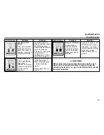
Страница 17: ...larm activates TWA Alarm Fast siren downward tone Fast flash Black box around gas flashes Vibrator alarm activates High Alarm Fast siren downward tone Fast flash Black box around gas flashes Vibrator alarm activates STEL Alarm Fast siren downward tone Fast flash Black box around gas flashes Vibrator alarm activates LOW ALARM 0 0 H2S ppm 0 LEL 0 CO ppm 19 5 O2 15 0 H2S ppm 20 9 O2 0 LEL 0 CO ppm TW...

Страница 18: ...nabled if the detector is to be used in accordance with performance requirements for European certification Alarm Screen Alarm Screen Multi Alarm Alternating low and high alarm siren and flash Black box around gas flashes Type of alarm alternates Vibrator alarm activates Over Limit OL Alarm Fast siren downward tone Fast flash Black box around gas flashes Vibrator alarm activates Note LCD may also ...

Страница 19: ...pliance beep and IntelliFlash automaticallydeactivate during a low battery alarm calibration fail bump test fail self test fail and in an alarm condition Critical Battery Alarm Fifteen minutes after low battery alarm activates sequence of 10 rapid sirens and alternating flashes with 1 second of silence in between sequence reactivates seven times Vibrator alarm pulses Low Battery Powering Off displ...

Страница 20: ...rs maximum Enter information such as employee name plant area emergency number s etc Lockout on Self Test Error If Lockout on Self Test Error is enabled and a failure occurs during the self test the screen displays Sensor Self Test Error Lockout Enabled and the detector deactivates Safe Mode If enabled SAFE displays continuously on the LCD unless an alarm condition occurs Confidence Compliance Bee...

Страница 21: ...isplay option is enabled the LCD is viewed at 180 upside down Stealth When enabled the following features are disabled backlight audible alarms visual alarms IntelliFlash and confidence compliance beep Only the vibrator and the LCD readings activate during an alarm condition Note Should the user wish to comply with European performance certifications stealth mode must be disabled Datalog Interval ...

Страница 22: ...each sensor Refer to Sample Gas Alarm Setpoints for factory defined alarm setpoints in the GasAlertQuattro User Manual High Alarm Define the high alarm setpoints for each sensor Refer to Sample Gas Alarm Setpoints for factory defined alarm setpoints in the GasAlertQuattro User Manual TWA Alarm The time weighted average TWA is a safety measure used to calculate accumulated averages of gases Using t...

Страница 23: ...on Enable 10 LEL of reading Over Span to ensure the detector is in compliance with CAN CSA C22 2 No 152 20 8 Base Reading If enabled the detector is configured to detect 20 8 O2 as ambient air When disabled the detector is configured to detect 20 9 O2 as ambient air Low Alarm Acknowledge If enabled the audible alarm can be temporarily disabled during a low alarm by pressing C The vibrator alarm LE...

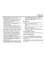
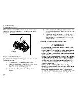
Страница 24: ...ase tab engages Tighten the retaining screw if required Charging the Rechargeable Battery Pack a WARNING To avoid personal injury and or damage to the detector adhere to following Charge only in a safe area that is free of hazardous gas within temperatures of 32 F to 104 F 0 C to 40 C Charge the battery immediately when the detector emits a low battery alarm Charge the lithium battery pack using t...

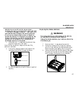
Страница 25: ...ncrease if the detector is activated 2 Connect the charging adapter to the detector IR receptacle Refer to the following illustration 3 The lithium battery may require 6 hours to reach full capacity Replacing the Alkaline Batteries a WARNING To avoid personal injury and or damage to the detector use only BW recommended alkaline batteries Change the alkaline batteries only in safe area that is free...

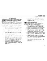
Страница 26: ...its original flat position Ensure the ejector bar engages the release clasp 7 Insert the new batteries Position the positive end of the battery at a 30 angle and insert into the battery pack before pushing the negative end down Ensure the batteries are not inserted over the tab Note Ensure all three batteries are inserted with the positive end pointing toward the top of the battery pack ...

Страница 27: ...of the Alkaline Battery Pack Removal and Disposal of the Rechargeable Battery Pack Dispose of the battery pack according to local laws Removal and Disposal of the Coin Cell The detector contains a coin cell to power the real time clock Only a qualified technician should complete the following procedure 1 Press and hold C to deactivate the detector 2 If the battery pack has not yet been removed ref...

Страница 28: ...ttro Quick Reference Guide Replacing the Sensors Battery pack Machine screws 6 Rear shell O sensor 2 H S sensor 2 Sensor filter with gasket Front shell LEL sensor CO sensor Side facing front shell Side facing sensors ...

Страница 29: ...detector 8 Replace the six machine screws using 3 4 in lbs torque Do not overtighten the screws Replace the battery pack 9 New sensors must be calibrated prior to use Wait a period of time before calibrating in order to allow stabilization Calibrate the new sensor s Refer to Calibration on page 10 Replacing the Sensor Filter To replace the filter refer to the illustration Replacing the Sensors on ...

Страница 30: ...200 ppm 0 1 ppm increments from 0 0 to 39 9 ppm 1 ppm increments above 40 ppm CO 0 1000 ppm 1 ppm increments O2 0 30 0 vol 0 1 vol increments Combustible LEL 0 100 1 LEL increments or 0 5 0 v v methane Sensor type H2S CO O2 Single plug in electrochemical cell Combustibles Plug in catalytic bead O2 measuring principle Capillary controlled concentration sensor Bump test specified limits BW recommend...

Страница 31: ...ent Year of manufacture The detector s year of manufacture is determined from the serial number The second and third number after the second letter determines the year of manufacture E g QA111 001000 2011 year of manufacture Approved lithium battery for GasAlertQuattro product Lithium ion polymer QT BAT R01 as per standards UL913 EN 60079 11 EN60079 0 IEC 60079 0 IEC 60079 11 EN 60079 29 1 EN 5010...

Страница 32: ...ed in the following manner Operating manual Read and understand the operating manual It is essential that the instructions for correct use are followed Instrument power up The instrument must be powered up in a safe area that is free of hazardous gas and in an atmosphere of 20 9 oxygen The detector must be turned on and verified to be operating in the normal measurement mode before it can be broug...

Страница 33: ...below the standard safety related limit values to allow enough time for protective measures to be carried out Instrument configuration FleetManager II version 2 6 0 or higher must be used to make configuration changes to the GasAlertQuattro To conform with configuration requirements for European gas performance Latching alarms must be enabled See page 16 Stealth mode must be disabled See page 17 F...

Страница 34: ...hall be reduced Measuring gases of other installed measuring channels of the GasAlertQuattro e g hydrogen sulphide may decrease the sensitivity of the LEL sensor The calibration interval should be reviewed taking into account any degradation in performance Methane LEL measurement performance as tested by BAM Methane response time t90 15 seconds Stabilization time for methane sensor 120 seconds War...

Страница 35: ...indicated as OL 4 Sensor cross sensitivities shall be considered For further information contact BW Technologies by Honeywell or an authorized agent 5 Some types and concentrations of dust in the measured atmosphere may impair the measuring function of the gas detector Performance Data According to EN 45544 1 Part 1 and 2 Target Gas CO H2S Time of response 13s 10s Time of recovery 15s 10s Alarm re...

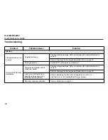
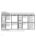
Страница 36: ...t BW Technologies by Honeywell Detector automatically deactivates Automatic deactivation due to critical low battery Replace alkaline batteries Refer to Replacing the Alkaline Batteries on page 21 Refer to Charging the Rechargeable Battery Pack on page 20 Lockout on Self Test Error is enabled and a sensor s has failed the startup self test Refer to Replacing the Sensors on page 24 and Lockout on S...

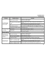
Страница 37: ...gies by Honeywell Sensor error Refer to Startup Troubleshooting on page 36 If required refer to Replacing the Sensors on page 24 Detector Operation Detector does not display normal gas reading after startup sequence Sensors not stabilized Used sensor Wait 60 seconds New sensor Wait 5 minutes Sensor s requires calibration Refer to Calibration on page 10 Target gas is present Detector is operating p...

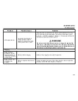
Страница 38: ...ual Define the alarm setpoints in FleetManager II Detector is in calibration mode Complete the calibration procedure Detector intermittently enters alarm without reason Ambient gas levels are near alarm setpoint or the sensor is exposed to a puff of the target gas Detector is operating normally Use caution in suspect areas Check peak gas exposure reading Alarm setpoints are set incorrectly Refer t...

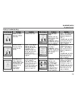
Страница 39: ...ernal power source or charger to operate the detector in a hazardous environment The chargers intended for use with the GasAlertQuattro detector are not certified for use in hazardous or potentially explosive environments Charging Battery has been charging for 6 hours Charging indicator on LCD shows the battery is still charging Battery is trickle charging Battery is fully charged and is ready for...

Страница 40: ... detector Refer to Calibration on page 10 If Cal IR Lock is enabled an IR device IR Link or MicroDock II must be used to calibrate All Sensors Fail If the Lockout on Self test Error option is enabled and all sensors fail the detector automatically deactivates A failure of all sensors can be caused by poisoning alcohol and silicon Allow sensors to recover for 1 hour If sensors fail startup again re...

Страница 41: ... bump test overdue Refer to Bump Test on page 12 Force Bump Test If the Force Bump Test option is enabled the sensors must be bump tested to enter normal operation Apply gas immediately or use the MicroDock II station otherwise press C to deactivate the detector Refer to Bump Test on page 12 BW recommends to bump test the sensors before each day s use to confirm their ability to respond to gas by ...

Страница 42: ...GasAlertQuattro User Manual For automated calibration refer to the MicroDock II User Manual Self test Fail If a sensor s fails auto zero an error message displays showing which sensor s failed Replace the sensor or contact BW Technologies by Honeywell Refer to Replacing the Sensors on page 24 Calibration Error Insufficient amount of gas detected Verify the span gas values on the cylinder match the...

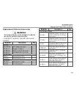
Страница 43: ...Regulators REG DF 1 Demand flow regulator 1 REG 0 5 0 5 l min regulator 1 Model No Description Qty Gas Cylinders and Kits CG Q58 4 Quad gas cylinder CH4 2 5 O2 18 0 H2S 25 ppm CO 100 ppm bal N2 58 l 1 CG Q34 4 Quad gas cylinder CH4 2 5 O2 18 0 H2S 25 ppm CO 100 ppm bal N2 34 l 1 CG T34 Dual gas cylinder 50 LEL CH4 2 5 O2 20 9 bal N2 34 l 1 G0042 H25 Single gas cylinder H2S 25 ppm bal N2 58 l 1 CG2...

Страница 44: ...B1 IR GasAlertQuattro IR connectivity kit 1 DOCK2 2 1 C1N 00 N GasAlertQuattro docking module 1 MicroDock II station w charging cable DOCK2 0 1C1N 00 N GasAlertQuattro docking module w charging cable 1 Accessories GA BQT Concussion proof boot 1 GA HQT Carrying holster 1 Model No Description Qty QT AF K1 Auxiliary Filter w LCD protector with 1 filter 1 QT SS AF K1 Replacement auxiliary filters kit ...

Страница 45: ......

Страница 46: ......

Страница 47: ......

Страница 48: ...50104941 536 EN Rev F 2017 BW Technologies by Honeywell All rights reserved ...

Отзывы: