background image

GAS 222.20 Ex1

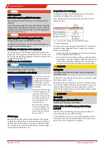
DANGER

Use in explosive areas

Flammable gas or dust atmospheres could ignite or explode.
Avoid the following hazard sources:

Application area!

Never operate the gas probe outside the specifications.
Sampling gases or gas mixtures which are also explosive in
the absence of air is prohibited.

Electrostatic charge (sparking)!

The equipment may only be used where normal operating
conditions do not frequently produce flammable, electro-
static discharge.

Always clean plastic housing parts and decals with a damp
cloth.

Sparking!

Protect the M3 connectors from external blows.

Flame propagation!

If the process holds a risk of flame propagation, install a
flame arrestor.

Adiabatic compression (explosion hazard)

Adiabatic compression may cause high temperatures during
blowback. Never blowback if explosive gas or dust atmo-
spheres are present. Only use nitrogen (inert gas) to blowback
flammable gas.

Dust

If possible, take the electrical components which must be
opened for repair to a dust-free room. If unable to do so, pre-
vent dust from entering the housing.

Zonal carryover when sampling from zone 20, 21, 22

If the particle size of the dusts being filter is smaller than the
fineness of the filter elements used, zonal carryover from the
process to the probe must be expected.

The fineness of the filter elements used must be clearly smal-
ler than the average particle size of dusts in the process gas.

Dust ignition

Regularly clean dust from all components. Dust layers > 5 mm
may have lower smouldering temperatures and the dust
layer could potentially ignite at a temperature below its
smouldering temperature.

Also remove dust under the thermal insulation and from the
gas probe heating tape.

The ignition temperature and smouldering temperature of
flammable dusts or dust layers which are present must be
above the marked surface temperature plus a safety factor
(also see section "Dust atmosphere requirements").

2.3 Equipment Ambient Temperatures

The ambient temperature range may be limited based on the
version. Please note the Ambient temperature ranges under
"Technical Data” in the full operating instructions.

2.4 Permissible gas inlet temperature

The permissible gas inlet temperatures between versions will
vary based on the temperature class of the gas in den outer
zones (see chapter "Technical Data" in the full operating in-
structions).

3 Transport and storage

Only transport the product inside the original packaging or a
suitable alternative.

The equipment must be protected from moisture and heat
when not in use. They must be stored in a covered, dry and
dust-free room at a temperature between -20 °C to 50 °C (-4 °F
to 122 °F).

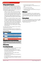
4 Installation and connection

NOTICE

Accessories may limit critical operating parameters of
the base unit

Adding accessories may limit critical operating parameters.
Ambient temperatures, zone classifications, explosion
groups, temperature classes or chemical resistances of ac-
cessories may vary from the base unit.

Always include all technical data in the operating instructions
and data sheets of all components in the safety assessment.

4.1 Installation site requirements

Sample gas probes are intended for flange mounting.

• Installation site and installation position are determined

based on requirements specific to the application.

• If necessary, the connection piece should be slightly tilted

toward the centre of the channel.

• The installation site should be protected from the

weather.

• In addition, adequate and safe access for installation and

future maintenance work should be provided. Particularly
follow the uninstalled size of the probe tube!

If the probe is transported to the installation site in pieces, it
will first need to be assembled.

4.2 Installation

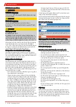
DANGER

Danger to life and explosion during installation and
maintenance

The unit must not be worked on (assembly, installation,
maintenance) in explosive atmospheres.

DANGER

Explosion hazard

When used in explosive areas

Flammable gasses and dust could ignite or explode.

Never operate the gas probe outside the specifications. Ex-
tracting gases or gas mixtures which are also explosive in the
absence of air is prohibited.

13

Bühler Technologies GmbH

BX460041 ◦ 03/2021

Содержание GAS 222.20 Ex1

Страница 1: ...60041 Version 03 2021 Ref 998BX460041 Analysentechnik Kurzanleitung Sonden deutsch 2 Brief Instructions Probes english 10 Notice de montage Sondes fran ais 16 Gu a r pida Sondas espa ol 23 chinese sim...

Страница 2: ...ner m glichen Explo sionsgefahr nicht erlaubt Prozessgase oder Prozessgasgemi sche d rfen keine Feststoffe enthalten die in Kombination mit den Materialien der Sonden inklusive Filter und Entnah meroh...

Страница 3: ...rtungsbereich des Betreibers unter Zuhilfe nahme seiner Risikobetrachtung Einschr nkungen der Kategorien Zonen durch Zubeh r Es ist zu beachten dass je nach verwendetem Zubeh r der zu gelassene Einsat...

Страница 4: ...Haftung durch die B hler Techno logies GmbH ausgeschlossen die im Datenblatt und der Anleitung angegebenen Grenz werte eingehalten werden das Griffst ck samt O Ring mit geeignetem Umgebung stemperatur...

Страница 5: ...Beachtung der Vorschrift IEC EN 60079 14 Zus tzliche nationale Bestimmungen bez glich Inbetrieb nahme Betrieb Wartung Instandhaltung und Entsorgung sind einzuhalten GEFAHR Elektrische Spannung Gefahr...

Страница 6: ...chichten m ssen oberhalb der ge kennzeichneten Oberfl chentemperatur liegen und um einen Sicherheitsfaktor erg nzt sein siehe auch Abschnitt Anfor derungen an die Staubatmosph re 2 3 Umgebungstemperat...

Страница 7: ...al muss den Anwendungsvoraussetzungen entsprechen und wetterfest sein 4 6 Anschluss der Gasleitung Die Messgasleitung ist mittels geeigneter Verschraubung sorgf ltig und fachgerecht anzuschlie en Dies...

Страница 8: ...utzvor schriften Der Hersteller des Heizbandes empfiehlt in re gelm igen Abst nden den Isolationswiderstand des Heizbandes zu messen Der Isolationswiderstand ist dabei zwischen kurzgeschlossenen Kupfe...

Страница 9: ...usf hrliche Beschreibung des Ger tes mit Hinweisen zur Fehlersuche und Reparatur finden Sie in der Originalbe triebsanleitung auf der beigef gten CD oder im Internet un ter www buehler technologies co...

Страница 10: ...em perature class for zone 0 1 for zone 1 ATEX II 1G 2G Ex db1 eb mb2 IIC T5 T6 T1 T2 Ga Gb ATEX II 2G Ex db1 eb mb2 IIC T6 T2 Gb IECEx Ex db1 eb mb2 IIC T5 T6 T1 T2 Ga Gb IECEx Ex db1 eb mb2 IIC T6 T...

Страница 11: ...ng highly ignitable dusts with a minimum ignition energy MIE of 3 mJ When sampling gas from Zone 2 ceramic sampling tubes may only be used if application and process related intensive electrostatic ch...

Страница 12: ...andatory maintenance is performed Legal regulations are observed during disposal compliance with national installation regulations NOTICE Accessories may limit critical operating parameters of the bas...

Страница 13: ...may be limited based on the version Please note the Ambient temperature ranges under Technical Data in the full operating instructions 2 4 Permissible gas inlet temperature The permissible gas inlet t...

Страница 14: ...ssible screw connection Shorten the connection pipe for the sample gas line as much as possible To do so remove the insulation around the sample gas line This is done by loosening the fixing bolts CAU...

Страница 15: ...lowback 5 Operation and Control NOTICE The device must not be operated beyond its specifications NOTICE The weather hood must be closed during operation DANGER Explosion hazard due to electrostatic di...

Страница 16: ...sonde de pr l vement de gaz n est pas autoris en raison d un risque d explosion Les gaz ou m langes de gaz in dustriels ne doivent pas contenir de mati res solides qui com bin es aux mat riaux des son...

Страница 17: ...t de l exploitant sur la base de son va luation des risques Limitations des cat gories zones du fait des accessoires Sachez que en fonction des accessoires utilis s le domaine d application autoris de...

Страница 18: ...ambiante appropri e et filtre le cas ch ant les dispositifs de surveillance le dispositif de protection sont correctement raccord s les travaux de maintenance et de r paration non d crits dans ce mod...

Страница 19: ...montage installation et main tenance ne doivent tre r alis s qu en absence d atmosph re explosive DANGER Utilisation dans des zones risque d explosion Les atmosph res charg es de gaz ou de poussi res...

Страница 20: ...une appartenance un groupe d explosion des classes de temp rature ou des r sistances chimiques diff rentes de ceux de l appareil de base Int grez toujours toutes les donn es techniques des instruc tio...

Страница 21: ...s s choisis soient plut t courts Raccourcissez le tube de raccordement de la conduite de gaz de mesure autant que possible Retirez pour cela le re v tement isolant voire les mors isolants dans la zone...

Страница 22: ...bo te de connexion voir sch ma en annexe pour l af fectation des contacts des bornes pour le branchement des lectrovannes en cas de r trolavage automatique son pr vues 5 Fonctionnement et utilisation...

Страница 23: ...gas de muestreo debido al posible riesgo de explosi n Los gases de proceso o las mezclas de gases de proceso no deben contener ning n s lido que en combinaci n con los materiales de las sondas incluid...

Страница 24: ...del operador con ayuda de su evaluaci n de riesgos Limitaciones de categor as zonas mediante accesorios Debe tenerse en cuenta que dependiendo de los accesorios utilizados el rango de aplicaci n permi...

Страница 25: ...La construcci n de instalaciones el ctricas en zonas con riesgo de explosi n requiere el cumplimiento de la norma IEC EN 60079 14 Tambi n deber n respetarse las restantes normativas na cionales relati...

Страница 26: ...ones No se permite la extracci n de gases mezclas de gases o polvos que puedan ser explosivos en presencia de aire Acumulaci n de electricidad est tica formaci n de chispas Los equipos el ctricos solo...

Страница 27: ...e especial atenci n a la longitud de ampliaci n del conducto de la sonda En caso de que la sonda se lleve al lugar de montaje por pie zas deber volver a montarse en primer lugar 4 2 Montaje PELIGRO Pe...

Страница 28: ...incorrecta puede destrozar el dispositivo Comprobar en la conexi n que la tensi n de red sea la correc ta de acuerdo con la placa indicadora CUIDADO Da os en el dispositivo Deterioro del cable No da e...

Страница 29: ...control necesarios est n disponibles y operativos por ej barrera contra llamas las salidas y entradas de gas de la sonda de gas de mues treo no est n bloqueadas se cumplen los par metros de entorno la...

Страница 30: ...x db1 eb mb2 IIC T5 T6 T1 T2 Ga Gb IECEx Ex db1 eb mb2 IIC T6 T2 Gb 0 21 20 1 ATEX II 1G 2D Ex db1 eb mb2 llC T5 T1 Ga Ex tb mb2 lllC T80 C T226 C Db ATEX II 1D 2G Ex ta lllC T120 C T300 C Da Ex db1 e...

Страница 31: ...0 1 21 0 21 11 Ex1 20 Ex1 21 Ex1 4622200205 4622200210 4622200215 2 1 21 2 21 MIE 3 mJ 2 1 2 T80 C T120 C T130 C T175 C T226 C T300 C 5 mm 155 C 195 C 205 C 250 C 301 C 375 C 120 C 180 C 195 C 263 C 3...

Страница 32: ...GAS 222 20 Ex1 IEC EN 60079 14 a b c d a b c a b c M3 20 21 22 5 mm 2 3 2 4 3 20 C 50 C 4 F bis 122 F 4 32 B hler Technologies GmbH BX460041 03 2021...

Страница 33: ...222 20 Ex1 4 1 4 2 4 3 4 4 O O O 90 4 5 4 6 GAS 222 1 DN65 PN6 DN3 150 G3 4 NPT 1 4 1 6 mm 1 4 1 1 NPT 1 4 4 6 1 6 mm 1 4 6mm 1 4 4 7 100 C 212 F 100 C 212 F 33 B hler Technologies GmbH BX460041 03 2...

Страница 34: ...GAS 222 20 Ex1 4 7 1 4 7 2 30 mA RCD 2500 V DC 10 MOhm 5 5 1 O 6 CD www buehler technologies com 7 CD www buehler technologies com 34 B hler Technologies GmbH BX460041 03 2021...

Страница 35: ...T6 T2 Gb IECEx Ex db1 eb mb2 IIC T5 T6 T1 T2 Ga Gb IECEx Ex db1 eb mb2 IIC T6 T2 Gb 0 21 20 1 ATEX II 1G 2D Ex db1 eb mb2 llC T5 T1 Ga Ex tb mb2 lllC T80 C T226 C Db ATEX II 1D 2G Ex ta lllC T120 C T...

Страница 36: ...Ex1 30 Ex1 31 Ex1 46222307 46222307F 2 1 20 21 20 1 2 21 11 Ex1 20 Ex1 21 Ex1 46222026 46222026P 2 1 20 21 20 1 2 21 11 Ex1 20 Ex1 21 Ex1 46222001 462220011 46222006 46222004 46222016 46222017 4622201...

Страница 37: ...58 GAS 222 20 Ex1 000092697 462222010149420013111 001 230V valve 24V UC B hler Technologies GmbH Harkortstr 29 D 40880 Ratingen IBExU17ATEX1088X IECEx IBE 17 0024X Ex eb mb IIC T4 Gb II 2G IECEx Ex eb...

Страница 38: ...GAS 222 20 Ex1 IEC EN 60079 14 a b c d a b c a b c M3 38 B hler Technologies GmbH BX460041 03 2021...

Страница 39: ...GAS 222 20 Ex1 20 21 22 5 2 3 2 4 3 20 C 50 C 4 F 122 F 4 4 1 4 2 4 3 39 B hler Technologies GmbH BX460041 03 2021...

Страница 40: ...GAS 222 20 Ex1 4 4 90 4 5 4 6 GAS 222 1 DN65 PN6 DN3 150 G3 4 NPT 1 4 1 6 1 4 1 1 NPT 1 4 4 6 1 6 1 4 6 1 4 4 7 100 C 212 F 100 C 212 F 40 B hler Technologies GmbH BX460041 03 2021...

Страница 41: ...GAS 222 20 Ex1 4 7 1 4 7 2 30 2500 DC 10 M 5 5 1 6 www buehler technologies com 7 www buehler technologies com 41 B hler Technologies GmbH BX460041 03 2021...

Страница 42: ...GAS 222 20 Ex1 1 Appendix 1 1 Probe Terminal Diagram Probe heater Blowback solenoid valve Sample gas solenoid valve i i 42 B hler Technologies GmbH BX460041 03 2021...

Отзывы: