


2007 Buell Ulysses: Maintenance
1-17
HOME
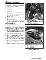
Bleed Front Brake
NOTE
Hydraulic brake fluid bladder-type pressure equipment can be
used to fill the brake master cylinder through the bleeder
valve if master cylinder reservoir cover is removed to prevent
pressurization.
1.
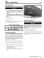
See
Figure 1-8.
With motorcycle upright, install end of
plastic tubing over front caliper bleeder valve and place
other end in a clean container.
CAUTION
D.O.T. 4 brake fluid will damage painted and body panel
surfaces it comes in contact with. Always use caution
and protect surfaces from spills whenever brake work is
performed. Failure to comply can result in cosmetic dam-
age. (00239a)
2.
Cover body surfaces, right handlebar switches and
instrument panel to protect from spillage.
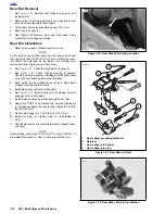
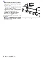
3.
See
Figure 1-9.
Remove two fasteners and reservoir
cap, stiffener and diaphragm.
4.
Repeat the following steps until all air bubbles are
purged and brake fluid flows from the plastic tubing.
a. See
Figure 1-10.
With motorcycle upright, add
D.O.T. 4 BRAKE FLUID to master cylinder reservoir
until the level matches level indicator in reservoir.
NOTE
Do not reuse brake fluid.
b. Slowly squeeze and release brake lever several
times to build up hydraulic pressure, then squeeze
or apply pressure to brake lever.
c. Open bleeder valve about 1/2-turn counterclock-
wise. Brake fluid will flow from bleeder valve and
through tubing into container.
d. When brake lever has moved 1/2 to 3/4 of its range
of travel, close bleeder valve (clockwise).
e. Allow brake lever to return slowly to its released
position.
5.
Tighten front caliper bleeder valve (metric) to 36-60 in-
lbs (4-7 Nm).
6.
Verify fluid level at reservoir indicator.
7.
Install diaphragm, stiffener and cap to front master cylin-
der reservoir and tighten fasteners to 9-13 in-lbs (1.0-
1.5 Nm).
8.
Remove protective cover from molded-in-color surfaces,
right handlebar switches and instrument panel.
Figure 1-8. Front Caliper Bleeder Valve (cap removed)
Figure 1-9. Fasteners, Cap, Stiffener and Diaphragm
Figure 1-10. Reservoir Fluid Level Indicator
11136
11147
11142
Содержание 2007 ULYSSES
Страница 17: ...A 16 2007 Buell Ulysses Appendix A HOME NOTES ...
Страница 35: ...B 18 2007 Buell Ulysses Electrical HOME 2007 Ulysses Model Main Harness 2007 Ulysses Model Main Harness ...
Страница 51: ...D 2 2007 Buell Ulysses Appendix D HOME Figure D 2 Rear Brake Systems Top View b1115acsxu ...
Страница 52: ...2007 Buell Ulysses Appendix D D 3 HOME Figure D 3 Rear Brake Systems Left Side View b1116adsxu ...
Страница 63: ...D 14 2007 Buell Ulysses Appendix D HOME NOTES ...
Страница 73: ......
Страница 103: ...1 30 2007 Buell Ulysses Maintenance HOME NOTES ...
Страница 129: ......
Страница 237: ...2 108 2007 Buell Ulysses Chassis HOME NOTES ...
Страница 239: ......
Страница 309: ...3 70 2007 Buell Ulysses Engine HOME NOTES ...
Страница 347: ...3 108 2007 Buell Ulysses Engine HOME NOTES ...
Страница 351: ...4 2 2007 Buell Ulysses Fuel System HOME Upper tie bar 25 27 ft lbs 33 9 36 6 Nm page 4 102 ITEM TORQUE NOTES ...
Страница 391: ...4 42 2007 Buell Ulysses Fuel System HOME NOTES ...
Страница 481: ......
Страница 505: ......
Страница 561: ...6 56 2007 Buell Ulysses Drive Transmission HOME NOTES ...
Страница 563: ......
Страница 587: ...7 24 2007 Buell Ulysses Electrical HOME NOTES ...
Страница 645: ...7 82 2007 Buell Ulysses Electrical HOME NOTES ...
Страница 647: ......