


7-10
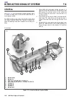
2007 Buell Ulysses: Electrical
HOME
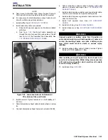
INSTALLATION
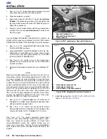
NOTE
When installing the ignition switch it is important to have the
fork lock pin pointing down while sliding the switch into place.
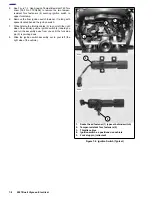
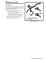
1.
See
Figure 7-4.
While holding the throttle cables (3) to
your left (the right side of the vehicle), slide the ignition
switch assembly in to your right (the left side of the vehi-
cle).
2.
Install the ignition switch (4) with the fork stop pin (5)
pointing down and, once in place, roll the assembly
toward you and insert the fork stop pin into the upper tri-
ple clamp.
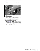
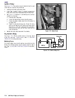
3.
See
Figure 7-5.
After applying LOCTITE 271 (red) attach
ignition switch assembly to upper triple clamp using igni-
tion switch fasteners (6,7). Tighten to 18-20 ft-lbs (24.4-
27.1 Nm).
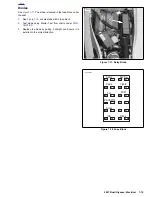
4.
See
Figure 7-7.
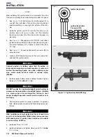
Connect ignition switch connector [33] to
wiring harness.
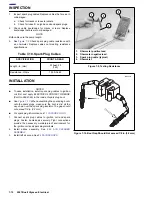
5.
Loosely install cable strap around the main wiring har-
ness and the ignition switch.
1
WARNING
1
WARNING
Connect positive (+) battery cable first. If positive (+)
cable should contact ground with negative (-) cable con-
nected, the resulting sparks can cause a battery explo-
sion, which could result in death or serious injury.
(00068a)
6.
Install negative battery cable to battery terminal. Tighten
fastener to 72-96
in-lbs
(8-11 Nm).
1
WARNING
1
WARNING
DO NOT modify the ignition/headlight switch wiring to
circumvent the automatic-on headlight feature. Visibility
is a major concern for motorcyclists. Failure to have
proper headlight operation could result in death or seri-
ous injury.
7.
Check ignition switch for proper operation. If operation
fails, reread procedure and verify that all steps were per-
formed.
1
WARNING
1
WARNING
After installing seat, pull upward on front of seat to be
sure it is in locked position. While riding, a loose seat can
shift causing loss of control, which could result in death
or serious injury. (00070a)
8.
Install seat. See
2.45 SEAT.
9.
Install windscreen and tighten fasteners to 10-12
in-lbs
(1.1-1.4 Nm).
Figure 7-7. Ignition Key Switch Wiring
4
4
3
3
2
2
1
1
Ignition Key Switch
Ignition Key Switch
Connector [33]
b1228x1x
R/GY
R
R
R
R
R/GY
R/BK
R/BK
8902
8904
Содержание 2007 ULYSSES
Страница 17: ...A 16 2007 Buell Ulysses Appendix A HOME NOTES ...
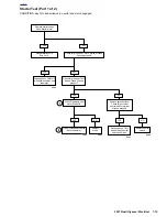
Страница 35: ...B 18 2007 Buell Ulysses Electrical HOME 2007 Ulysses Model Main Harness 2007 Ulysses Model Main Harness ...
Страница 51: ...D 2 2007 Buell Ulysses Appendix D HOME Figure D 2 Rear Brake Systems Top View b1115acsxu ...
Страница 52: ...2007 Buell Ulysses Appendix D D 3 HOME Figure D 3 Rear Brake Systems Left Side View b1116adsxu ...
Страница 63: ...D 14 2007 Buell Ulysses Appendix D HOME NOTES ...
Страница 73: ......
Страница 103: ...1 30 2007 Buell Ulysses Maintenance HOME NOTES ...
Страница 129: ......
Страница 237: ...2 108 2007 Buell Ulysses Chassis HOME NOTES ...
Страница 239: ......
Страница 309: ...3 70 2007 Buell Ulysses Engine HOME NOTES ...
Страница 347: ...3 108 2007 Buell Ulysses Engine HOME NOTES ...
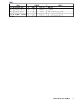
Страница 351: ...4 2 2007 Buell Ulysses Fuel System HOME Upper tie bar 25 27 ft lbs 33 9 36 6 Nm page 4 102 ITEM TORQUE NOTES ...
Страница 391: ...4 42 2007 Buell Ulysses Fuel System HOME NOTES ...
Страница 481: ......
Страница 505: ......
Страница 561: ...6 56 2007 Buell Ulysses Drive Transmission HOME NOTES ...
Страница 563: ......
Страница 587: ...7 24 2007 Buell Ulysses Electrical HOME NOTES ...
Страница 645: ...7 82 2007 Buell Ulysses Electrical HOME NOTES ...
Страница 647: ......