


2007 Buell Ulysses: Engine
3-51
HOME
Replacing Valve Guides
Valve guide replacement, if necessary, must be done before
valve seat is ground. It is the valve stem hole in valve guide
that determines seat grinding location. Valve stem-to-valve
guide clearances are listed in
Table 3-18.
If valve stems and/
or guides are worn beyond limits, install new parts.
1.
To remove shoulderless guides, press or tap guides
toward combustion chamber using VALVE GUIDE
REMOVER/INSTALLER (Part No. B-45524).
2.
Clean and measure valve guide bore in head.
3.
Measure outer diameter of a new standard valve guide.
The guide diameter should be 0.0020-0.0033 in.
(0.0508-0.0838 mm). larger than bore in head. If clear-
ance is not within specification, select oversize valve
guide and machine valve guide O.D. as needed.
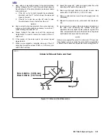
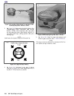
4.
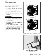
See
Figure 3-70.
Install shoulderless guides using
VALVE GUIDE REMOVER/INSTALLER TOOL (Part No.
B-45524). Press or drive guide until the tool touches the
machined surface surrounding the guide. At this point,
the correct guide height has been reached.
5.
Ream guides to final size or within 0.0010 in.
(0.0254 mm) of final size using VALVE GUIDE REAMER
(Part No. B-45523). Use REAMER LUBRICANT (Part
No. HD-39964) or liberal amounts of suitable cutting oil
to prevent reamer chatter.
NOTE
The hone is not intended to remove material.
6.
Apply the proper surface finish to the valve guide bores
using the VALVE GUIDE HONE (Part No. B-45525).
Lubricate hone with honing oil. Driving hone with an
electric drill, work for a crosshatch pattern with an angle
of approximately 60°.
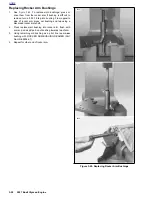
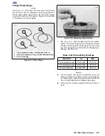
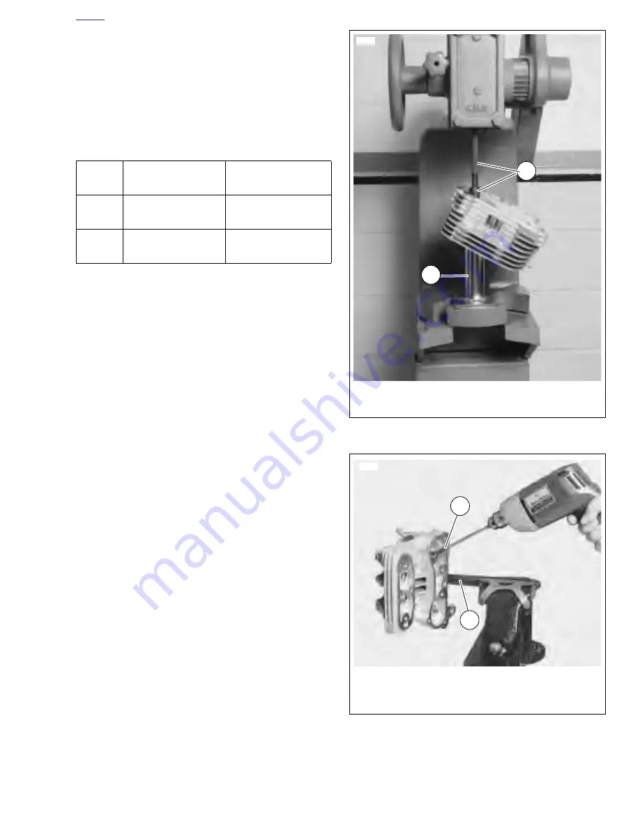
7.
See
Figure 3-71.
Thoroughly clean valve guide bores
using VALVE GUIDE BRUSH (Part No. HD-34751) and
hot soapy water.
Table 3-18. Valve Stem Clearances
and Service Wear Limits
VALVE
CLEARANCE
SERVICE WEAR
LIMIT
Exhaust
0.001-0.003 in.
(0.025-0.076 mm)
0.0035 in.
(0.0889 mm)
Intake
0.001-0.003 in.
(0.025-0.076 mm)
0.0035 in.
(0.0889 mm)
Figure 3-70. Installing Shoulderless Valve Guide
Figure 3-71. Cleaning Valve Guides
1.
Valve guide remover/installer (Part No. B-45524)
2.
Cylinder head stand (Part No. HD-39782)
1
2
5692
5695
1.
Valve guide brush (Part No. HD-34751)
2.
Cylinder head holding fixture
(Part No. HD-39786)
1
2
Содержание 2007 ULYSSES
Страница 17: ...A 16 2007 Buell Ulysses Appendix A HOME NOTES ...
Страница 35: ...B 18 2007 Buell Ulysses Electrical HOME 2007 Ulysses Model Main Harness 2007 Ulysses Model Main Harness ...
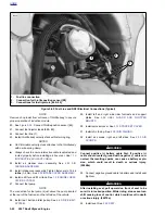
Страница 51: ...D 2 2007 Buell Ulysses Appendix D HOME Figure D 2 Rear Brake Systems Top View b1115acsxu ...
Страница 52: ...2007 Buell Ulysses Appendix D D 3 HOME Figure D 3 Rear Brake Systems Left Side View b1116adsxu ...
Страница 63: ...D 14 2007 Buell Ulysses Appendix D HOME NOTES ...
Страница 73: ......
Страница 103: ...1 30 2007 Buell Ulysses Maintenance HOME NOTES ...
Страница 129: ......
Страница 237: ...2 108 2007 Buell Ulysses Chassis HOME NOTES ...
Страница 239: ......
Страница 309: ...3 70 2007 Buell Ulysses Engine HOME NOTES ...
Страница 347: ...3 108 2007 Buell Ulysses Engine HOME NOTES ...
Страница 351: ...4 2 2007 Buell Ulysses Fuel System HOME Upper tie bar 25 27 ft lbs 33 9 36 6 Nm page 4 102 ITEM TORQUE NOTES ...
Страница 391: ...4 42 2007 Buell Ulysses Fuel System HOME NOTES ...
Страница 481: ......
Страница 505: ......
Страница 561: ...6 56 2007 Buell Ulysses Drive Transmission HOME NOTES ...
Страница 563: ......
Страница 587: ...7 24 2007 Buell Ulysses Electrical HOME NOTES ...
Страница 645: ...7 82 2007 Buell Ulysses Electrical HOME NOTES ...
Страница 647: ......