Buell 2007 ULYSSES Скачать руководство пользователя страница 635

7-72

2007 Buell Ulysses: Electrical

HOME

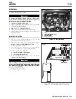
24. Remove any remaining cable straps and clamps secur-

ing wire harness and remove harness from front of vehi-
cle.

25. Pull the main harness out through the rear of the frame/

fuel tank assembly into the trunk pan.

NOTE

Using scissors jack, raise vehicle higher to gain more clear-
ance between the trunk pan and tire.

26. Remove all tree fasteners from the frame.

INSTALLATION

NOTES

See 

Figure 7-88.

 Always align harness when installing in the

frame and tail section. Align the harness so both ECM wire
bundles, the dyno loop and the main ground all face upward
so when they are installed the harness will not be twisted.

For more information on wire harness and hose routing, see

HOSE AND WIRE ROUTING

.

1.

Install the new harness from the rear of the vehicle work-
ing towards the front.

2.

Feed front and center portion of harness from the trunk
pan through opening at rear of frame/fuel tank assembly.

3.

Place connectors in general location of installation.

4.

Secure plastic harness holder to left inside portion of
frame using new plastic tree fasteners.

5.

Be sure to route the interactive exhaust cable behind the
harness strap with main harness.

NOTE 

Fuel line is installed under engine connector portion of wire
harness.

6.

See 

Figure 7-85.

 Install clamp over portion of harness

that leads to engine connectors. Install clamp as shown
using new plastic tree fastener.
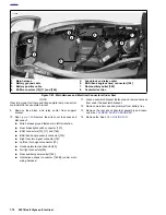
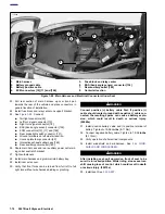
7.

See 

Figure 7-86.

 Route portion of main wire harness that

contains the positive battery cable (3), sprocket cover
wiring (4) and transmission vent hose (2) through corner
mounting strap and guide (1) at rear of frame. Install new
plastic tree fasteners.

Figure 7-85. Wire Harness Clip

8837a

Figure 7-86. Wire Harness Strap and Guide

8838

4

2

1

3

1.

Mounting strap and guide

2.

Transmission vent hose

3.

Positive battery cable

4.

Sprocket cover wiring

5.

Tree fastener (2)

5

Содержание 2007 ULYSSES

Страница 1: ...UELL ULYSSES SERVICE MANUAL Part Number 99494 07Y Section 1 Maintenance Section 2 Chassis Section 3 Engine Section 4 Fuel System Section 5 Starter Section 6 Drive Transmission Section 7 Electrical Appendices ...

Страница 2: ...art No HD 28431 B Black Light Fluorescent Additive Use with HD HD 25070 HD 26792 HD 28431 6 Fluorescent Additive 6 1 oz bottles HD 28431 22 Fluorescent Additive 1 22 oz container HD 28431B Part No HD 33223 1 Cylinder Compression Gauges Part No HD 33416 Universal Driver Handle Part No HD 33418 Universal Puller Forcing Screw h33223 HD33416 h33418 ...

Страница 3: ...o HD34736 B Valve Spring Compressor Part No HD 34751 Nylon Valve Guide Brush h33446 b1001a3x h34726B h34751 Part No HD 34902 B Mainshaft Primary Bearing Race Remover And Installer Part No HD 35102 Wrist Pin Bushing Hone 20 mm Part No HD 35316 C Main Drive Gear Remover Installer and Main Drive Gear Bearing Installer Part No HD 35457 Black k Light Leak Detector h34902b h35102 HD 35316C h35457 ...

Страница 4: ...hso bho knsdl hlno hslnslp pffb odlbndpob npond bndb ndbno bho Bdhgkjsbkdv ksjjlkn lk knsdl hlno hslnsln nlslns finbp pffb odlbndpob nponno bho knsdl hlno hslnsln nlslns finbp pklhb odlbndpob npdb ndbno bho knsdl hlno hslnslnnsdl hlno hso bho bs npond bpdk kznh odlbndpob npond bndb ndbno bho Bdhgkjsbkdv ksjjlkn lk knsdl hlno hslnsln nlslns finbp pffb odlbndpob nponno bho knsdl hlno hslnsln nlslns ...

Страница 5: ...t No HD 39782 A Cylinder Head Support Stand Part No HD 39786 Cylinder Head Holding Fixture HD 39565 HD39617 h39782 h39786 Part No HD 39964 Reamer Lubricant Cool Tool Part No HD 39965 Deutsch Terminal Crimp Tool Part No HD 39969 Ultra Torch UT 100 Part No HD 39978 Fluke 78 Multimeter DVOM F HD39964 HD39965 HD 39969 HD39978 ...

Страница 6: ...lamp Pliers Part No HD 41155 VHS Tape Storage Rack Part No HD 41177 Fork Tube Holder HD 41025 A HD 41137 HD41155 2 b41177 94 Part No HD 41185 Hose Cutting Tool Part No HD 41334 RPM Inductive Pickup Part No HD 41354 Speedometer Tester Part No HD 41404 Harness Connector Test Kit HD 41185 HD39617 h41354 HD41404 ...

Страница 7: ...t No HD 41475 100 Deutsch Connector Pick Tool Part No HD 41496 Main Drive Gear Seal Installer HD 41417 h41475 h41475 100 HD41496 Part No HD 41609 Amp Terminal Crimp Tool Part No B 41623 B Oil Line Remover Part No HD 41675 Oil Pressure Sending Unit Wrench Part No HD 42310 Engine Transmission Stand HD39965 B41623 HD41675 h42310a ...

Страница 8: ... HD 42320 A Piston Pin Extractor Part No HD 42322 Piston Support Plate h42310 150a h42311a h42320a h42322 Part No HD 42326 A Crankshaft Guide Part No HD 42376 Battery Load Tester Part No B 42887 Brake Caliper Piston Remover Part No HD 43646 A Rolling Engine Stand h42326 600 200 Made in USA PP 9606 0001 h42376a b42887 h43646a ...

Страница 9: ...iver Part No B43982 Transmission Locking Tool Part No HD 43984 Crankshaft Locking Tool h43682 10a b43721 b 43982 hd43984 Part No B 43987 Engine Cradle Part No B 43993 Wheel Bearing Collets Part No HD 44060 Wheel Bearing Remover Installer Part No HD 44067 A Oil Filter Wrench b43987a B 43993a hd44060 hd44067b ...

Страница 10: ...t Adapter Part No HD 44720 TSSM Adapter Cable h44358bc h44567 h44687 HD44720a Part No HD 44750 P29 Panasonic Toughbook touch screen and HD 44750 P50 Panasonic Toughbook non touch screen Part No B 45520 Gear Detente Assembly Aid Part No B 45521 Steering Head Bearing Remover Installer Part No B 45522 Fuel Pressure Gauge Adapter HD 44750 b45520 b45521 B 45522a ...

Страница 11: ...5524 Valve Guide Installer Part No B 45525 Valve Guide Hone Part No B 45657 Fuel Pump Puller B 45523 B 45524 B 45525 b45657 Part No B 45676 Sprocket Shaft Seal Installer Part No HD 45830 Techlink Kit Part No HD 45835 Road Test Kit Part No B 45847 Cross Plate B 45676 hd45830a HD45835a B43983 ...

Страница 12: ...Bearing Remover Part No HD 45928 Terminal Crimper Part No HD 45929 Terminal Remover h45907 b45926 HD45928 HD4529 Part No HD 45966 Front Fork Compressor Part No B 46279 7 8 Axle Wrench Hex Part No HD 46283 Primary Drive Locking Tool Part No HD 46285 Transmission Assembly Fixture HD45996a B 46279 HD 46283 HD 46285 ...

Страница 13: ...Penlight Part No HD 47184 Leak Detector Flashlight Part No HD 47187 Technician Pen Light HD 46288 HD 47183 HD 47184 HD 47187 Part No HD 47188 Technician Flex Light Part No HD 47248 Rocker Housing Wrench Part No HD 47250 Intake Manifold Wrench Part No HD 47258 Rocker Cover Wrench HD 41788 HD 47248 HD 47250 HD 47258 ...

Страница 14: ...tery Conductance and Electrical System Analyzer Part No J 5586 Transmission Shaft Retaining Ring Pliers HD 47855 HD 48030a HD 48053A J 5586A Part No B 59000 B Oil Level Gauge Part No HD 94660 37B Mainshaft Locknut Wrench Part No HD 94804 57 Rocker Arm Bushing Reamer Part No HD 95635 46 All Purpose Claw Puller use with HD 95637 46A 0 0 0 0 0 1 2 3 4 5 60 mL HD59000B HD 94660 37B HD 95635 46 ...

Страница 15: ...tems 6 HD 95769 69 7 HD 95770 69 and 8 HD 95771 69 are optional Part No HD 95952 33C Connecting Rod Clamping Tool Part No HD 95970 32D Piston Pin Bushing Tool h95637 46A h95760 69B h95952 33C h95920 32D Part No HD 96333 51E Piston Ring Compressing Tool Part No HD 96550 36B Valve Lapping Tool Part No HD 96796 Valve Spring Test Fixture Part No HD 96921 52B h96333 51C h96550 36A 96796 47 h96921 52C ...

Страница 16: ...2007 Buell Ulysses Appendix A A 15 HOME Part No HD97097 65B Hose Clamp Pliers Part No HD 99500 80 Wheel Truing Balancing Stand h97081a HD99500 80a ...

Страница 17: ...A 16 2007 Buell Ulysses Appendix A HOME NOTES ...

Страница 18: ...ll terminal from chamber Do not tug on the wire until the tang is released or the terminal will be difficult to remove A click is heard if the tang is engaged but then inadvertently released Repeat the step without releasing the tang NOTE If pick tool is not available a push pin safety pin may be used instead An ELECTRICAL TERMINAL CRIMP TOOL Part No HD 41609 is used to install Amp Multi lock pin ...

Страница 19: ...Gently tug on wire end to verify that the terminal is locked in place and will not back out of chamber 3 Rotate the hinged secondary lock inward until tabs fully engage latches on both sides of connector 4 Insert the socket housing plug into the pin housing receptacle until it snaps in place 5 Install connector on retaining device either attachment or rosebud clip Figure B 2 Release Tang and Back ...

Страница 20: ...1 Socket terminal Secondary lock Socket housing Pin housing Pin terminal Latch Secondary lock Button Latch Socket terminal Secondary lock Button Socket housing Pin housing Secondary lock Pin terminal 3 place 6 place 12 place Secondary locks open socket housings shown Stamped numbers on secondary locks indicate wire color locations d0245x2x ...

Страница 21: ...p tails until ends make contact with locking bar Verify that wire is positioned so that short pair of crimp tails squeeze bare wire strands while long pair folds over insulation material 5 Squeeze handle of crimp tool until tightly closed Tool automatically opens when the crimping sequence is complete Raise up locking bar and remove contact 6 Inspect the quality of the core and insulation crimps D...

Страница 22: ... to separate the pin and socket halves Two three four and six pin Deutsch connectors have one external latch while eight and twelve pin connectors have two both of which must be pressed simultaneously to separate the connector halves NOTE With few exceptions the socket housing can always be found on the accessory side while the pin side of the connector is connected to the wiring harness REMOVING ...

Страница 23: ...ll terminals are fully installed in the socket housing The lock indicates when terminals are not properly installed by not entering its fully installed position REMOVING INSTALLING PINS 1 Remove the secondary locking wedge Use the hooked end of a stiff piece of mechanics wire a needle nose pli ers or a suitable pick tool Part No HD 41475 100 See Figure B 10 2 Gently depress terminal latches inside...

Страница 24: ...on the socket side must be aligned with the latch cover on the pin side For those connectors with two external latches 8 pin and 12 pin a different system is used to prevent improper assembly Align the tabs on the socket housing with the grooves on the pin housing Push the connector halves together until the latches click If latches do not click latch press on one side of the connector until that ...

Страница 25: ...its snugly in the space between the contact band and the core crimp tails 4 Strip lead removing 5 32 in 4 mm of insulation Insert wires between crimp tails until ends make contact with locking bar Verify that wire is positioned so that short pair of crimp tails squeeze bare wire strands while long pair folds over insulation material 5 Squeeze handle of crimp tool until tightly closed Tool automati...

Страница 26: ...minal 2 Wire seal 3 Socket housing 4 External latch 5 Internal seal 6 Locking wedge 7 Locking wedge 8 Latch cover 9 Pin housing 10 Wire seal 11 Pin terminal SOCKET SIDE PIN SIDE 1 2 4 5 6 7 8 9 10 11 3 2 pin connector 1 2 4 3 5 6 7 8 10 11 9 3 pin connector 1 2 4 5 6 7 8 9 10 11 3 4 pin connector d0251x3x ...

Страница 27: ...side the chamber For an example of this type of connector note the MAP sensor connector 80 Unlike most connectors where the terminals are pulled out the wire end of the connector to remove the terminals from the pull to seat connectors the terminal is pushed out the mating end of the connector Once a new terminal is crimped onto the end of the wire the wire is pulled to draw the termi nal back ins...

Страница 28: ...nals that have been extracted on a previ ous occasion no clicking sound may be heard when the pin is pivoted to depress the tang but proceed as if the clicking is audible and then push on the wire end of the lead to check if the terminal is free When picking multiple terminals the end of the pin may become malleable For best results continue the proce dure with a new safety pin 5 Remove the pin an...

Страница 29: ...he secondary lock take note of the larger cavity next to each terminal 5 Insert the pick Snap On TT600 3 into the cavity until it stops Pivot the end of the pick toward the terminal to depress the locking tang Remove the pick and gently tug on the wire to pull the terminal from the wire end of the connector Repeat the step if the terminal is still locked in place NOTE A series of Packard Electrica...

Страница 30: ...pair folds over insulation or seal material 7 Squeeze handle of crimp tool until tightly closed Tool automatically opens when the crimping sequence is complete 8 Table B 1 Determine the correct dye or nest for the insu lation seal crimp 9 Lay the back of the insulation seal crimp tails on the appropriate nest Be sure the insulation seal crimp tails are pointing towards the forming jaws 10 Squeeze ...

Страница 31: ...t connector 4 place Amp behind windscreen 39 instrument module 20 place Multilock in front modules behind windscreen 45 license plate lamp 2 1 place bullet under rear wire cover 46 stator 4 place Deutsch under sprocket cover 65 vehicle speed sensor 3 place Deutsch under sprocket cover 77 voltage regulator 2 place Packard under sprocket cover 83 ignition coil 3 place Packard beneath aircleaner base...

Страница 32: ...gen sensor 1 place Packard behind rear cylinder head 160 Front auxiliary power outlet 2 place Sumitomo 161 Interactive exhaust to actuator 4 place Amp under airbox cover 164 Interactive exhaust circuit to ECM spade terminal under seat 165 Interactive exhaust subharness to main harness 3 place Deutsch under seat 178 Active intake system to solenoid 2 place Deutsch under airbox cover 179 Active inta...

Страница 33: ...INDEX TO WIRING DIAGRAMS B 5 Table B 3 Wiring Diagrams DIAGRAM PAGE Main harness B 17 Engine management circuit B 18 Lighting circuit B 19 Horn and instruments circuit B 20 Starting circuit B 21 Charging circuits B 22 Component Circuits B 23 ...

Страница 34: ...BE O Y BE Y BE W Y BK Y BN Y BK GY W V R LT GN R LT GN Y PK Y W BK W BK O Y V GY GN W V Y 1 10 2 2 2 5 3 3 3 3 IGNITION KEY SW START 4 4 4 4 5 5 5 7 6 6 6 8 15 7 7 7 6 13 8 8 8 9 14 9 9 9 2 10 10 10 19 12 12 12 20 19 18 17 16 15 14 13 11 11 11 11 1 1 2 1 3 4 1 5 6 2 7 2 8 1 2 3 4 5 6 1 2 3 4 5 1 1 A A 1 1 1 2 2 B B 2 2 2 IGN 3 3 C C 3 3 3 4 4 D D 4 4 4 A A A 1 1 B B B 2 2 C A B C C C 3 3 1 1 1 1 1...

Страница 35: ...B 18 2007 Buell Ulysses Electrical HOME 2007 Ulysses Model Main Harness 2007 Ulysses Model Main Harness ...

Страница 36: ... 1 1 B B B B 2 2 C C C C 3 3 1 1 1 1 1 1 2 2 2 2 2 2 DIODE BATTERY COOLING FAN IGNITION ECM KEY SWITCH 1 90A ENGINE TEMP SENSOR 90B 131A 1 165A 161A ACTIVE MUFFLER SUB HARNESS 2 1 3 TN V O W O 36 42 BRAKE HORN MUFFLER TN V W 1 HALL SENSOR CONTROL SIGNAL GROUND Vbat MUFFLER VALVE ACTUATOR MOTOR SENSOR POSITION DC CONTROL ELECTRONICS TN V O TN V W BK O W 1 2 3 1 1 4 4 3 3 2 2 165B 161B ECM SENSOR PO...

Страница 37: ...B 20 2007 Buell Ulysses Electrical HOME 2007 Ulysses Model Engine Management Circuit 2007 Ulysses Model Engine Management Circuit ...

Страница 38: ...K O W V R Y BK W Y O W V R BK R BK R BE O W R BK 10 87 87 87A 87A 30 30 85 85 86 86 KEY SW START 7 8 15 6 13 14 2 19 11 1 2 1 3 4 1 5 1 6 2 7 2 8 1 2 3 4 5 1 1 1 2 2 2 IGN 3 3 3 4 4 4 1 1 1 1 1 1 2 2 1 2 2 2 BATTERY BRAKE HORN MUFFLER ACCESSORY LIGHTS KEY SWITCH 0 2 4 3 1 0 0 1 R 1 USER USER 1 R BK R GY BATTERY BATTERY 1 R 0 0 0 PARK KEY POSITION IGNITION SWITCH WIRING DIAGRAM CONNECTING WIRE SECT...

Страница 39: ...B 22 2007 Buell Ulysses Electrical HOME 2007 Ulysses Model Lighting Circuit 2007 Ulysses Model Lighting Circuit ...

Страница 40: ...ODE BATTERY BRAKE HORN MUFFLER IGNITION KEY SWITCH 131A 1 0 2 4 3 1 0 0 1 R 1 USER USER 1 R BK R GY BATTERY BATTERY 1 R 0 0 0 PARK KEY POSITION IGNITION SWITCH WIRING DIAGRAM CONNECTING WIRE SECT mm WIRE COLOR ON OFF LOCK TACHOMETER OUTPUT SYSTEM GROUND B BANK ANGLE SENSOR ACTIVE MUFFLER FEEDBACK INJECTOR REAR OUTPUT REAR COIL PRIMARY FRONT COIL PRIMARY INJECTOR FRONT OUTPUT CHECK ENGINE LAMP FUEL...

Страница 41: ...B 24 2007 Buell Ulysses Electrical HOME 2007 Ulysses Model Horn Instruments Circuit 2007 Ulysses Model Horn Instruments Circuit ...

Страница 42: ...N Y BK BK GN TN Y R BK R BK R BK GN R BK TN LT GN BK R GY O GY O BK W BK R R BK TN LT GN W BK 10 5 87 87A 30 85 86 3 IGNITION KEY SW START 4 7 8 15 6 13 9 14 2 19 11 1 1 1 2 2 2 IGN 3 3 3 4 4 4 1 1 2 DIODE IGNITION KEY SWITCH 131A 1 MALE FEMALE 0 2 4 3 1 0 0 1 R 1 USER USER 1 R BK R GY BATTERY BATTERY 1 R 0 0 0 PARK KEY POSITION IGNITION SWITCH WIRING DIAGRAM CONNECTING WIRE SECT mm WIRE COLOR ON ...

Страница 43: ...B 26 2007 Buell Ulysses Electrical HOME 2007 Ulysses Model Starting Circuit 2007 Ulysses Model Starting Circuit ...

Страница 44: ...s Model Charging Circuit BATTERY CABLE SOLENOID STARTER MOTOR 128A 46B 46A HD 3 PHASE STATOR REGULATOR VOLTAGE 77A 77B TO VOLTAGE REGULATOR GRD2 STARTER BATTERY BK 2 1 1 4 4 3 3 2 2 2 1 1 R BK R R Y BK 24 BATTERY 30A 30 FUSE RELAY ASSEMBLY 61B bs0021au ...

Страница 45: ...B 28 2007 Buell Ulysses Electrical HOME 2007 Ulysses Model Charging Circuit 2007 Ulysses Model Charging Circuit ...

Страница 46: ...L LAMP REAR TURNING LIGHTS TO MAIN HARNESS RH TURN SIGNAL TAIL LIGHT 93A 19A 45A 18A LH TURN SIGNAL LIC PLATE LAMP TO MAIN HARNESS STATOR REGULATOR VOLTAGE 128A BATTERY CABLE SOLENOID STARTER BATTERY MOTOR STARTER GRD2 77A 46A 165B 46B 161B 161A 77B TO VOLTAGE REGULATOR HD 3 PHASE FUEL PUMP VEHICLE SPEED SENSOR 65A RH CONTROLS LH CONTROLS HORN 22B 24B 31B 31B RH TURN SIGNALS LH TURN SIGNALS 122B 2...

Страница 47: ...B 30 2007 Buell Ulysses Electrical HOME 2007 Ulysses Model Component Circuits 2007 Ulysses Model Component Circuits ...

Страница 48: ... 449 4 488 4 527 4 567 4 606 4 645 4 685 4 724 4 764 4 803 4 842 001 002 003 004 005 006 007 008 009 010 1 64 020 030 1 32 040 050 060 1 16 070 080 090 1 1 8 3 16 2 1 4 3 5 16 3 8 4 7 16 1 2 9 16 025 051 076 102 127 152 178 203 229 254 397 508 762 794 1 016 1 270 1 524 1 588 1 778 2 032 2 286 2 540 3 175 4 762 5 080 6 350 7 620 7 938 9 525 10 160 11 112 12 700 14 288 6 5 8 11 16 7 3 4 8 13 16 7 8 ...

Страница 49: ...SH IMPERIAL SYSTEM Fluid volume measurements in this Service Manual do not include the British Imperial Imp system equivalents The fol lowing conversions exist in the British Imperial system 1 pint Imp 20 fluid ounces Imp 1 quart Imp 2 pints Imp 1 gallon Imp 4 quarts Imp Although the same unit of measure terminology as the U S system is used in the British Imperial Imp system the actual volume of ...

Страница 50: ...2007 Buell Ulysses Appendix D D 1 HOME HOSE AND WIRE ROUTING D 1 Figure D 1 Front and Rear Brake Systems Right Side View b1114absxu ...

Страница 51: ...D 2 2007 Buell Ulysses Appendix D HOME Figure D 2 Rear Brake Systems Top View b1115acsxu ...

Страница 52: ...2007 Buell Ulysses Appendix D D 3 HOME Figure D 3 Rear Brake Systems Left Side View b1116adsxu ...

Страница 53: ...D 4 2007 Buell Ulysses Appendix D HOME Figure D 4 Evaporative Emissions Control California Models Top View b1117acsxu Carbon canister ...

Страница 54: ...HOME Figure D 5 Evaporative Emissions Control California and 49 State Models Left Side View 1 To induction module 2 From induction module California 3 From fuel tank California 4 From fuel tank to atmosphere 49 state 1 b1118acsxu 2 3 4 ...

Страница 55: ...Buell Ulysses Appendix D HOME Figure D 6 Wiring Harness Left Side View 1 To active intake solenoid Japan only 2 Intake air temperature sensor IAT 3 Fuel pump 4 Active intake to ECM Japan only 2 b1119absxu 3 1 4 ...

Страница 56: ...2007 Buell Ulysses Appendix D D 7 HOME Figure D 7 Wiring Harness Top View 1 Fuel injector 2 2 Throttle position sensor TPS 3 Intake air temperature IAT sensor 4 Oxygen O2 sensor 2 3 4 b1120acsxu 1 ...

Страница 57: ...x D HOME Figure D 8 Wiring Harness Right Side View 1 Speedometer sensor 2 Cable starter to battery positive 3 Solenoid 4 Transmission vent line 5 Voltage regulator 6 Switch oil pressure 7 Cam position sensor 2 3 6 b1121xdsxu 1 4 5 7 ...

Страница 58: ...D D 9 HOME Figure D 9 Oil Lines Right Side View 1 Vent line 2 Feed oil line 3 Return oil line 4 Feed oil line from the oil pump to the oil cooler 5 Return oil line from the oil cooler to the oil filter housing b1122absxu 1 4 5 2 3 ...

Страница 59: ...D 10 2007 Buell Ulysses Appendix D HOME Figure D 10 Oil Lines Bottom View 1 Vent line 2 Feed oil line 3 Return oil line b1123absxu 1 3 2 ...

Страница 60: ...2007 Buell Ulysses Appendix D D 11 HOME Figure D 11 Clutch Cable and Exhaust Valve Actuator Right Side View b1124absx Muffler valve Exhaust valve actuator ...

Страница 61: ...D 12 2007 Buell Ulysses Appendix D HOME Figure D 12 Clutch Throttle Seat Release Cables and Exhaust Valve Actuator Left Side View b1125acsxu Muffler valve Exhaust valve actuator Cable seat lock ...

Страница 62: ... Buell Ulysses Appendix D D 13 HOME Figure D 13 Clutch Throttle Seat Release Cables and Exhaust Valve Actuator Top View Cable seat lock b1126acsxu EVA mounted on top of functional airbox cover TPS adjuster ...

Страница 63: ...D 14 2007 Buell Ulysses Appendix D HOME NOTES ...

Страница 64: ...e 22 flow charts Using TEST CONNECTOR KIT Part No HD 41404 attach Brown pin probe and patch cord to 179 1 2 VERIFY SETTINGS 1 Prior to verifying the active intake system check the throttle position sensor TPS zero and adjust if neces sary See 1 19 THROTTLE POSITION SENSOR TPS 2 Leave Digital Technician attached to vehicle 3 In Digital Technician go to Active Intake test screen 4 Rotate throttle gr...

Страница 65: ...ing off the throttle you should be able to move the solenoid shaft slightly inward until the shaft bottoms out This slight travel will be the retraction freeplay NOTE This freeplay is necessary for the solenoid to properly func tion Freeplay should be 1 32 in 0 79 mm or greater c If you have no travel in the shaft adjust cable hous ing 4 away from the solenoid bracket 3 until free play is achieved...

Страница 66: ...hich should be 1 32 in 0 79 mm or greater c If you have no travel in the shaft loosen jam nuts 2 and adjust cable housing 4 towards the solenoid bracket 3 until freeplay is achieved 4 See VERIFY SETTINGS Once freeplay has been set it will be necessary to verify settings and adjustments again If values are not between 10 4 10 9 degrees see Throttle Stop Screw in this section Figure E 2 Checking for...

Страница 67: ...ust stop screw while reading the TPS on Digital Technician until setting is between the range of 10 4 to 10 9 a If the reading is below 10 4 adjust screw clockwise b If the reading is above 10 9 adjust screw counter clockwise 5 Reconfirm the TPS setting Repeat process if needed 6 Adjust active intake cable assembly See CABLE ADJUSTMENT 7 Verify active intake TPS settings 8 Install cosmetic intake ...

Страница 68: ...2007 Buell Ulysses Appendix E E 5 HOME Figure E 4 Active Intake System 1 1 2 2 J1 J3 J4 J2 11A 164A 179B 179A 10A GY O W GY Active Intake Solenoid Control Signal ECM ...

Страница 69: ...ery voltage present NO Measure resistance between connector 178A pin 1 and 179B pin 1 Continuity present NO NO Clean and repair connections Disconnect active solenoid connector 179B at ECM Measure resistance at pin 2 to chassis ground Resistance less than 10 000 ohms Repair short to voltage in GY O wire YES NO Repair open in GY O wire YES NO Repair short to ground in W GY wire Measure resistance b...

Страница 70: ...olenoid NO YES Connect battery voltage to 178B pin 2 of active intake solenoid Use HD 41404 brown pin and patch cable Hold throttle wide open Observe throttle plate and connect solenoid pin 1 to ground Does solenoid attempt to pull throttle almost closed NO Hold throttle wide open Energize active intake solenoid Does throttle close to an angle less than 11 degrees YES YES NO Replace ECM See CABLE ...

Страница 71: ...nstalling baseplate assembly 10 see 4 44 AIR CLEANER ASSEMBLY NOTE When installing the backing plate it is important to ensure that the active cable remains in the tower on the cable wheel on the throttle body If the cable comes out the cable will not work properly and will not be able to be adjusted NOTES When installing baseplate be sure to feed the electrical connector 1 through hole in basepla...

Страница 72: ... Drive Belt Maintenance 1 27 1 10 Primary Chain 1 31 1 11 Suspension Damping Adjustments 1 33 1 12 Steering Head Bearings 1 37 1 13 Spark Plugs 1 38 1 14 Air Cleaner Filter 1 40 1 15 Throttle Cable and Idle Speed Adjustment 1 42 1 16 Interactive Exhaust Cable 1 43 1 17 Ignition Timing 1 45 1 18 Headlights 1 47 1 19 Throttle Position Sensor TPS 1 49 1 20 Storage 1 50 1 21 Troubleshooting 1 51 MAINT...

Страница 73: ......

Страница 74: ...proper tools Protect yourself and bystanders with approved eye protection Don t just do the job do the job safely Removing Parts Always consider the weight of a part when lifting Use a hoist whenever necessary Do not lift heavy parts by hand A hoist and adjustable lifting beam or sling are needed to remove some parts The lengths of chains or cables from the hoist to the part should be equal and pa...

Страница 75: ...stall bearings with numbered side facing out Always use the proper tools and fixtures for removing and installing bearings Bearings do not usually need to be removed Only remove bearings if necessary Bushings Do not remove a bushing unless damaged excessively worn or loose in its bore Press out bushings that must be replaced When pressing or driving bushings be sure to apply pressure in line with ...

Страница 76: ...tting hardened wire unless they were designed for that purpose Always cut at right angles Don t use any prybar as a chisel punch or hammer Hammers Never strike one hammer against a hardened object such as another hammer Always grasp a hammer handle firmly close to the end Strike the object with the full face of the hammer Never work with a hammer which has a loose head Discard hammer if face is ch...

Страница 77: ...hes Replace sockets showing cracks or wear Keep sockets clean Always use approved eye protection when using power or impact sockets Storage Units Don t open more than one loaded drawer at a time Close each drawer before opening up another Close lids and lock drawers and doors before moving storage units Don t pull on a tool cabinet push it in front of you Set the brakes on the locking casters afte...

Страница 78: ...ou may find that some gasoline blends adversely affect the starting driveability or fuel efficiency of your bike If you expe rience one or more of these problems we recommend you try a different brand of gasoline or gasoline with a higher octane rating ENGINE OIL Use the proper grade of oil for the lowest temperature expected before the next oil change If it is necessary to add oil and Harley Davi...

Страница 79: ...djustment X X X X X X 1 Rear belt idler and sprockets Inspect X X X X X X Throttle brake and clutch con trols sidestand active muffler cable and active intake cable adj if equipped Check adjust and lubricate X X X X X X 1 Brake fluid Check levels and condition X X X X X X 1 2 Brake pads and discs Inspect for wear X X X X X X Spark plugs Replace X X 1 Electrical equipment and switches Check operati...

Страница 80: ... plug torque Apply Loctite 565 Thread Sealant and reinstall plug and tighten to 14 30 ft lbs 19 41 Nm Clutch adjustment Free play at adjuster screw clockwise 1 4 1 2 turn Free play at hand lever 1 16 1 8 in 1 6 3 2 mm Clutch inspection cover torque 84 108 in lbs 10 12 Nm Transmission lubricant Lubricant level FORMULA TRANSMISSION AND PRIMARY CHAINCASE LUBRICANT Part No 99851 05 as required until f...

Страница 81: ...33 in lbs 3 4 Nm Spark plugs Type 10R12A Gap 0 035 in 0 9 mm Torque 12 18 ft lbs 16 24 Nm Engine idle speed Idle speed 1050 1150 RPM Front fork oil Type HYDRAULIC FORK OIL TYPE E Part No 99884 80 4 45 in 113 mm from the top of the fork tube Battery Lubricant ELECTRICAL CONTACT LUBRICANT Part No 99861 02 1 oz Battery terminal torque 72 96 in lbs 8 11 Nm Table 1 2 Quick Reference Maintenance Chart I...

Страница 82: ...t in death or serious injury 00064a 1WARNING 1WARNING Battery posts terminals and related accessories contain lead and lead components chemicals known to the State of California to cause cancer and birth defects or other reproductive harm Wash hands after handling 00019a BATTERY TESTING Voltmeter Test Refer to Table 1 4 The voltmeter test provides a general indi cator of battery condition Check th...

Страница 83: ...ct the battery case for cracks or leaks STORAGE 1WARNING 1WARNING Batteries contain sulfuric acid which could cause severe burns to eyes and skin Wear a protective face shield rubberized gloves and protective clothing when working with batteries KEEP BATTERIES AWAY FROM CHIL DREN 00063a CAUTION Do not allow battery to completely discharge The elec trolyte in a discharged battery will freeze The mo...

Страница 84: ...en bolts on battery terminals Use rec ommended torque values Over tightening battery termi nal bolts could result in damage to battery terminals 00216a 3 Insert fastener through battery positive cable red into threaded hole of battery positive terminal and tighten fastener to 72 96 in lbs 8 11 Nm 4 Install terminal cover boot 5 Insert fastener through battery negative cable black into threaded hol...

Страница 85: ...rained more fre quently ENGINE OIL LEVEL CHECK CAUTION Do NOT operate the engine when the oil level is below the add mark on the dipstick at operating temperature Engine damage will result 00187a CAUTION Do not overfill oil tank Doing so can result in oil carry over to the air cleaner leading to equipment damage and or equipment malfunction 00190a CAUTION Do not switch lubricant brands indiscrimin...

Страница 86: ...l filter using pliers or belt type OIL FILTER WRENCH 3 Clean filter gasket contact surface on crankcase Surface must be smooth and free of debris or old gasket material 4 Apply a thin film of clean engine oil to filter gasket 5 Pour 4 0 ounces 0 12 liter of clean engine oil into new fil ter until filter is approximately 1 2 full 6 Screw filter onto adapter until filter gasket touches crank case su...

Страница 87: ...ressed air can pierce the skin and flying debris from compressed air could cause serious eye injury Wear safety glasses when working with compressed air Never use your hand to check for air leaks or to deter mine air flow rates 00061a 7 Blow out any debris from fins with compressed air from the inside of the oil cooler outward Inspect cooler fins for debris or damage 8 Wipe up any spilled oil on m...

Страница 88: ... death or seri ous injury 1WARNING 1WARNING Use only fresh uncontaminated D O T 4 fluid Cans of fluid that have been opened may have been contami nated by moisture in the air or dirt Use of contaminated brake fluid may adversely affect braking ability and lead to brake failure which could result in death or serious injury 1WARNING 1WARNING Use only new copper crush banjo washers See Parts Catalog ...

Страница 89: ...unting bolts Warped rotor Replace brake pads Replace rotor and bushings as set Tighten bolts Replace rotor and bushings as set Ineffective brake lever pedal travels to limit Low fluid level Piston cup not functioning Fill master cylinder with approved brake fluid and bleed system Rebuild cylinder Ineffective brake lever pedal travel normal Distorted or glazed rotor Distorted glazed or contaminated...

Страница 90: ...he plastic tubing a See Figure 1 10 With motorcycle upright add D O T 4 BRAKE FLUID to master cylinder reservoir until the level matches level indicator in reservoir NOTE Do not reuse brake fluid b Slowly squeeze and release brake lever several times to build up hydraulic pressure then squeeze or apply pressure to brake lever c Open bleeder valve about 1 2 turn counterclock wise Brake fluid will f...

Страница 91: ...id flows from the plastic tubing a With motorcycle upright add D O T 4 BRAKE FLUID to master cylinder reservoir until the level is between upper and lower marks on reservoir NOTE Do not reuse brake fluid b Slowly depress and release brake pedal several times to build up hydraulic pressure then hold brake pedal in the depressed position c While holding brake pedal in the depressed position open ble...

Страница 92: ...ement 5 1WARNING 1WARNING Threaded rod should not be adjusted to the point of con tacting brake pedal Improper adjustment could result in death or serious injury 1 See Figure 1 14 Inspect for minimum and maximum brake rod engagement in brake clevis 4 Adjust as required 2 To adjust brake pedal a See Figure 1 14 Loosen locknut 3 while holding rod adjuster 2 Move locknut away from top surface of clev...

Страница 93: ...r brakes when changing fluid Traction can be adversely affected which could result in loss of control of the motorcycle and death or serious injury 00047b See Figure 1 16 and Figure 1 17 Inspect and measure both front and rear brake rotors At every scheduled service interval 1 Inspect rotor Replace rotor if warped or badly scored 2 Measure rotor thickness Replace rotor if minimum thick ness is les...

Страница 94: ...e retracted and remove fluid from the reservoir if necessary 2 Push pistons in with suitable tool such as a clean paint scraper until fully seated in bores Be careful not to dam age rotor 3 Install new inner pad from left side of motorcycle 4 Install new outer pad from right side of motorcycle 5 See Figure 1 18 Install pin under pin 3 making sure it engages hole on both pads and spring clip 6 Rota...

Страница 95: ...dged install with widest area of spring towards piston side of caliper 4 Push piston in with suitable tool such as a clean paint scraper until fully seated in bore 5 Install new inner and outer brake pads 6 See Figure 1 21 Install hanger pin 4 making sure pin engages hole on both pads 7 Install brake caliper and carrier assembly over rotor 8 Apply LOCTITE 271 and install two mounting fasteners 1 t...

Страница 96: ...ining Replace the tires when the tire wear indicator bars appear New tires are needed if any of the following conditions exist 1 Tire wear indicator bars become visible on the tread sur faces 2 Tire cords or fabric become visible through cracked side walls snags or deep cuts 3 A bump bulge or split in the tire 4 Puncture cut or other damage to the tire that cannot be repaired WHEEL BEARINGS 1WARNI...

Страница 97: ... and washers from clutch inspec tion cover Remove clutch inspection cover with gasket from primary cover CAUTION Do not overfill the primary chaincase transmission with lubricant Overfilling can cause rough clutch engage ment incomplete disengagement clutch drag and or dif ficulty in finding neutral at engine idle 00199b IMPORTANT NOTE Make certain primary chaincase is filled with proper amount of...

Страница 98: ... is a large amount of free play at clutch hand lever 3 See Figure 1 24 Remove three fasteners and washers from clutch inspection cover Remove clutch inspection cover and gasket from primary cover 4 See Figure 1 28 Remove spring 1 and lockplate 2 Using a flat tip screwdriver turn adjusting screw 3 counterclockwise until it lightly bottoms 5 Turn adjusting screw clockwise 1 4 1 2 turn Install lock p...

Страница 99: ... Gap between ferrule and bracket should be 1 16 1 8 in 1 6 3 2 mm b See Figure 1 27 Set free play by turning adjuster 4 c Tighten jam nut 3 against adjuster 4 d Slide boot 1 over cable adjuster mechanism 7 Change or add transmission fluid if necessary NOTE Each time the clutch inspection cover is removed the gasket must be replaced 8 See Figure 1 24 Install clutch inspection cover and new gasket u...

Страница 100: ...ts are misaligned Outside surface for signs of stone puncture If cracks damage exists near edge of belt replace belt immedi ately Damage to center of belt will require belt replace ment eventually but when cracks extend to edge of belt belt failure is imminent Inside toothed portion of belt for exposed tensile cords normally covered by facing fabric This condition will result in belt failure and i...

Страница 101: ...oth wear Rough or damaged sprocket Inspect replace sprocket Worn sprocket Inspect replace sprocket Debris in sprocket Clean and protect drive Inspect for damaged or missing guards Abrasive environment Eliminate or control exposure Inspect for damaged or missing guards Apparent belt stretch NOTE The drive belt tension on a new belt will loosen after approximately 1000 mi 1600 km Worn sprocket Inspe...

Страница 102: ...et or belt Inspect replace sprocket Clean and protect drive Inspect replace belt Excessive drive noise Worn damaged sprocket Inspect replace sprocket Missing damaged belt guards Damaged flange Repair flange replace sprocket Damaged idler Check structure bad bearing bent members etc Replace idler assembly Damaged belt Follow proper handling installation procedure Inspect replace belt Debris stuck i...

Страница 103: ...1 30 2007 Buell Ulysses Maintenance HOME NOTES ...

Страница 104: ...If necessary adjust as described under 1 10 PRIMARY CHAIN in ADJUST MENT NOTE The initial primary chain vertical free play specification used at the assembly plant is 1 4 1 2 in 6 4 12 7 mm with a cold engine The 1 4 in 6 4 mm minimum is only allowed at the absolute tightest point in the drive as measured with special ized factory equipment If a chain has less than 1 4 in 6 4 mm vertical free play...

Страница 105: ...are worn beyond adjustment limits Replace parts as necessary See 6 5 PRI MARY CHAIN 1 See Figure 1 33 Loosen locknut 1 2 Turn adjusting fastener 2 a Clockwise inward to reduce free play b Counterclockwise outward to increase free play 3 Tighten locknut 1 to 20 25 ft lbs 27 34 Nm Figure 1 33 Chain Tension Adjusting Fastener 8403 1 Locknut 2 Adjusting Fastener 1 2 ...

Страница 106: ...in the load carried requires changes in the preload setting s Carrying less weight than was used for setting up the suspension requires decreasing the amount of preload Increasing the load carried requires adding more preload 1WARNING 1WARNING Do not exceed the motorcycle Gross Vehicle Weight Rat ing GVWR Exceeding the GVWR can affect stability and handling which could result in death or serious i...

Страница 107: ...sting the damping adjuster positions when operating outside the normal ambient temperature range of 65 95 F 18 35 C 1 Adjust suspension for rider weight Refer to Table 1 10 2 Reduce front and rear compression damping and rebound damping by turning adjuster counterclockwise 1 4 1 2 turn Table 1 10 Recommended Suspension Settings for Rider Weight RIDER AND CARGO WEIGHT FRONT FORK REAR SHOCK LB KG PR...

Страница 108: ...ing the adjuster nut 2 with a wrench Setting Front Fork Rebound Damping 1 See Figure 1 34 Using a screwdriver turn the slotted dial 1 clockwise until it stops This is the maximum rebound damping setting 2 Then turn the dial counterclockwise the recommended amount specified in Table 1 10 Setting Front Fork Compression Damping 1 See Figure 1 35 Using a screwdriver turn the slotted dial clockwise unt...

Страница 109: ...ed rebound adjustment dial clockwise until it stops This is the maximum rebound damping setting 2 Then turn the dial counterclockwise the number of turns recommended in Table 1 10 Setting Rear Shock Compression Damping 1 See Figure 1 38 Using a screwdriver turn the slotted dial clockwise until it stops This is the maximum com pression damping setting 2 Turn the dial counterclockwise the number of ...

Страница 110: ...nce turn front wheel all the way to the right 6 See Figure 1 39 Hook a spring scale into the hole in the front axle With scale 90 degrees from fork leg pull front wheel to center position a The desired resistance to pull front wheel to center is between 1 7 lbs 0 5 3 2 kg b If steering head resistance measurement is not within specification see DETERMINING PROPER RESISTANCE 7 When adjustment is co...

Страница 111: ...ec trodes and ceramic insulator tip indicates an oil fouled plug The condition may be caused by one or more of the following worn pistons worn piston rings worn valves worn valve guides worn valve seals a weak battery or a faulty ignition system b A dry fluffy or sooty black deposit indicates an air fuel mixture that is too rich and or engine idling for excessive periods c A light brown glassy dep...

Страница 112: ...1 Check electrode gap with a wire type feeler gauge Gap should be 0 035 in 0 9 mm 12 Apply LOCTITE ANTI SEIZE to threads of spark plugs Install and tighten spark plugs to 12 18 ft lbs 16 24 Nm NOTES Start threading rear spark plug with 3 8 fuel hose being careful not to cross thread spark plug Start front spark plug with fingers An extension may be needed to push on rear spark plug boot to ensure ...

Страница 113: ... 6 and remove air cleaner cover from baseplate 5 See Figure 1 44 Remove the filter element 1 from baseplate 2 Inspect and replace if necessary CAUTION See Figure 1 44 Cover the velocity stack so nothing can drop into the motor CLEANING AND INSPECTION 1WARNING 1WARNING Do not use gasoline or solvents to clean filter element Flammable cleaning agents can cause an intake system fire which could resul...

Страница 114: ...r cleaner cover and connect to fuel vent valve 7 Secure vent tube to vent valve with new cable strap 6 Install intake cover assembly with four fasteners and nylon washers Tighten fasteners to 12 36 in lbs 1 3 4 Nm 1WARNING 1WARNING After installing seat pull upward on front of seat to be sure it is in locked position While riding a loose seat can shift causing loss of control which could result in...

Страница 115: ... length 5 Point front wheel straight ahead Twist throttle control grip to fully open position hold in position 6 Turn adjuster on throttle control cable 2 until throttle cam stop touches stop plate Tighten cable adjuster lock on throttle control cable adjuster release throttle control grip 7 Turn handlebars fully to right Turn adjuster on idle con trol cable 3 until end of cable housing just touch...

Страница 116: ... of the housing 7 Release the cable core and reattach the cable to the cable wheel and bracket 8 Tighten jam nut CAUTION Do not overtighten jam nut on interactive exhaust cable 9 See Figure 1 48 Adjust interactive exhaust cable as fol lows a See Figure 1 47 Move cable with your fingers from side to side There should be no more than 1 8 in 3 2 mm side play in cable in either direction with 1 4 in 6...

Страница 117: ...2 before installing air intake cover CAUTION If cable is routed in front of the frame lug it will cause the muffler valve to stay open not allowing it to work prop erly 12 Install air intake cover See 2 39 INTAKE COVER ASSEMBLY Figure 1 49 Correct Cable Routing Behind Frame Lug Typical 10514a 1 Interactive exhaust cable 2 Frame lug 2 1 ...

Страница 118: ... using the rear wheel Position the flywheel TDC mark at the very left edge of the inspection hole 7 If the engine is coming up on the compression stroke for the FRONT correct cylinder the screen will be display ing LOW 0 volts with timing mark at left edge of window 8 Gently bump flywheel forward in tiny increments 9 See Figure 1 51 If the static timing is correct the screen will switch to HIGH 5 ...

Страница 119: ... advanced mark appears on left side of window rotate timing plate counterclockwise 3 Check timing See CHECKING STATIC TIMING 4 See Figure 1 55 If timing is retarded mark appears on right side of window rotate timing plate clockwise 5 Tighten sensor assembly fasteners to 15 30 in lbs 1 7 3 4 Nm 6 Recheck timing Figure 1 52 Timer Cover Figure 1 53 Cam Position Sensor 12136a 8391a Figure 1 54 Advance...

Страница 120: ...s Weight will compress vehicle suspension slightly 5 Stand motorcycle upright with headlights aimed straight forward 6 Check LOW beam right lens for alignment a See Figure 1 57 Turn ignition switch to IGN Set handlebar headlight switch to LOW beam position b Check that the correct pattern of light is a double rectangular pattern and is aligned with the horizontal line as shown in Figure 1 56 c Adj...

Страница 121: ...using to adjust the vertical alignment NOTE Only loosen headlight alignment fasteners enough to adjust headlight Once headlights are aligned tighten fasteners to 48 72 in lbs 5 8 Nm See Figure 1 59 The vertical headlight adjustment screw is located under the front upper fender Figure 1 58 Horizontal Headlight Adjustment 11792 11793 Figure 1 59 Vertical Headlight Adjustment Screw Figure 1 60 Front ...

Страница 122: ...hrottle control grip 2 3 times NOTE This is to ensure that the throttle plate is completely closed before beginning recalibration 7 With ignition and run switch in the on position with engine off and throttle in the closed position press the TPS zero button at the bottom of the screen 8 Select TPS zero button and perform TPS zero NOTE When calibration is complete dialogue box will appear on Digita...

Страница 123: ...otorcycle will be stored for an extended period of time securely support the motorcycle so that all weight is off the tires 1WARNING 1WARNING Be sure that brake fluid or other lubricants do not con tact brake pads or discs Such contact can adversely affect braking ability which could cause loss of control resulting in death or serious injury 00290a 7 Wash and polish molded in color painted and chr...

Страница 124: ...m CMP sensor See dealer 20 Inoperative fuel pump See dealer Starts Hard 1 Spark plugs in bad condition have improper gap or are partially fouled 2 Wires are crossed 3 ATC in stuck open 4 Spark plug cables in bad condition and shorting 5 Battery nearly discharged 6 Loose wire connection at one of the battery terminals at coil or at plug between ignition sensor and module 7 Throttle controls not adj...

Страница 125: ...of insufficient lubrication 5 Wheels not aligned and or tires worn 6 Internal engine problem 7 Wheels not balanced correctly ENGINE LUBRICATION SYSTEM Oil Does Not Return To Oil Tank 1 Oil tank empty 2 Return pump gears damaged 3 Oil feed pump not functioning 4 Restricted oil lines or fittings Engine Uses Too Much Oil or Smokes Excessively 1 Piston rings badly worn or broken 2 Valve stem seals wor...

Страница 126: ... Insufficient brake pedal or hand lever free play brake drags Handling Irregularities 1 Tires improperly inflated See 1 7 TIRES AND WHEELS Do not overinflate 2 Loose wheel axle Tighten front axle to 39 41 ft lbs 53 56 Nm Tighten rear axle to 48 52 ft lbs 65 70 Nm 3 Excessive wheel hub bearing play 4 Rims and tires out of true sideways tire runout should not be more than 0 080 in 2 03 mm 5 Rims and...

Страница 127: ...uspension seems not to respond to bumps This is evidenced by tire chattering a movement with short stroke and high frequency through corners or by jolting the rider over rough roads Reduce compression damping Table 1 12 Rear Suspension Problems TROUBLESHOOTING CONDITION ADJUSTMENT SOLUTION Pumping on the Rear occurs when you are accelerating out of a corner This problems occurs in two varieties 1 ...

Страница 128: ...r 2 62 2 21 Frame 2 63 2 22 Frame Pucks 2 64 2 23 Rear Shock Absorber 2 65 2 24 Throttle Control 2 67 2 25 Deflectors 2 68 2 26 Clutch Control Cable 2 69 2 27 Headlight Grill 2 73 2 28 Headlights and Support Bracket 2 74 2 29 Front Modules 2 77 2 30 Handlebars 2 79 2 31 Mirrors 2 81 2 32 Exhaust System 2 82 2 33 Rider and Passenger Footpegs 2 85 2 34 Heel Guard and Footpeg Mounts 2 86 2 35 Sprocke...

Страница 129: ......

Страница 130: ...ight Specifications WEIGHT LBS KG Wet weight 498 226 GVWR 950 431 GAWR front 345 156 GAWR rear 685 311 Load capacity 452 205 All measurements include a full tank of fuel Table 2 3 Capacities CAPACITIES U S LITERS Fuel tank inc reserve 4 4 gallons 16 7 Reserve Low fuel light at 0 83 gal lons 3 1 Oil tank wet for normal oil change 2 5 quarts 2 4 Fork oil each fork 15 35 ounces 0 45 Transmission 1 0 ...

Страница 131: ...r set front 11 14 ft lbs 15 19 Nm page 2 34 Brake pin hanger set rear 11 14 ft lbs 15 20 Nm page 2 43 Brake pin plug rear 24 in lbs 2 7 Nm page 2 43 Caliper banjo bolt front 16 20 ft lbs 22 27 Nm metric page 2 32 Caliper banjo bolt rear 16 20 ft lbs 22 27 Nm page 2 41 Caliper bleeder valves 36 60 in lbs 4 7 Nm metric page 2 27 Caliper carrier rear 24 26 ft lbs 32 35 Nm page 2 20 Caliper fasteners ...

Страница 132: ...ont isolator snubber upper 12 36 in lbs 1 4 Nm page 2 62 Front isolator threaded frame insert 59 61 ft lbs 80 82 7 Nm LOCTITE 271 page 2 62 Front muffler mount 16 18 ft lbs 1 7 24 4 Nm page 2 84 Hand lever pivot fastener 39 48 in lbs 4 4 5 4 Nm page 2 29 Handlebar clamp screws 10 12 ft lbs 14 16 Nm LOCTITE 271 red Tighten front screws first page 2 79 Headlight support bracket fas teners 48 72 in l...

Страница 133: ...red page 2 71 Shift pedal flange head bolt 22 24 ft lbs 30 32 5 Nm LOCTITE 271 red page 2 71 Shock absorber lower 15 17 ft lbs 20 3 23 Nm page 2 61 Shock mounting fastener upper 48 52 ft lbs 65 70 5 Nm page 2 66 Sidestand bracket fasteners 25 27 ft lbs 34 37 Nm LOCTITE 271 red page 2 105 Sprocket cover fastener 12 36 in lbs 1 4 Nm page 2 87 Sprocket fasteners 35 37 ft lbs 48 50 Nm Replace with new...

Страница 134: ...ME Upper module fasteners 36 60 in lbs 4 1 6 8 Nm page 2 77 Valve stem nut 40 44 in lbs 4 5 4 9 Nm page 2 23 Windscreen fasteners 10 12 in lbs 1 1 1 4 Nm page 2 100 Wire cover screws 36 48 in lbs 4 0 5 4 Nm page 2 107 ITEM TORQUE NOTES ...

Страница 135: ...7 x 3 5 MT DOT J designates the tire and rim standard 17 is the normal diameter of the rim in inches measured at the bead seat diameter 3 5 is the width of the bead seat measured in inches MT designates the rim type DOT means that the rim meets Department of Transpor tation Federal Motor Vehicle Safety Standards Refer to Table 2 7 Figure 2 1 Rim Markings 8423 Table 2 7 Tire Fitment Tubeless Cast W...

Страница 136: ...4MZ KP 01 D 3 7 3 0 00456 1 2 3 4 5 6 7 9 8 Table 2 8 Buell 2007 XB Models V I N Description ITEM DESCRIPTION POSSIBLE VALUES 1 WMI Code 4MZ Buell vehicles originally manufactured for sale within the United States 5MZ Buell vehicles originally manufactured for sale outside the United States 2 Motorcycle type KP Blast AX Firebolt KX Lightning CityX SX Lightning WX Lightning Scg JX Lightning Long DX...

Страница 137: ...rear axle See 2 6 REAR WHEEL Excessive side play or radial up and down play in wheel hubs Replace wheel bearings Rims and tires out of true sideways should not be more than 0 080 in 2 03 mm Replace rims See 2 7 CHECKING CAST RIM RUNOUT and 2 8 TIRES Rims and tires out of round or eccentric with hub should not be more than 0 090 in 2 29 mm Replace rims See 2 7 CHECKING CAST RIM RUNOUT and 2 8 TIRES...

Страница 138: ...ases small punctures in the tread area may be repaired from within the demounted tire by a Buell dealer Speed should NOT exceed 50 mph 80 km h for the first 24 hours after repair and the repaired tire should NEVER be used over 80 mph 130 km h Failure to follow this warn ing could result in death or serious injury 00118a 11WARNING 1WARNING Buell tires are equipped with wear bars that run horizon ta...

Страница 139: ...ht side lower fender fasteners See 2 36 FENDERS 3 See Figure 2 4 Loosen front axle pinch fasteners 2 on front fork 4 Remove axle 1 NOTES The front axle is left handed thread To prevent cosmetic damage to the wheel center caliper between spokes before removal 5 See Figure 2 5 Raise the wheel up until the rotor clears the caliper and rotate the fork leg counterclockwise allowing wheel clearance for ...

Страница 140: ...rt No HD 44060 4 See Figure 2 7 Insert the FRONT WHEEL BEARING REMOVER COLLET Part No B 43993 7 from kit Part No B 43993 50 into the wheel bearing until it fully seats against the bearing 5 Insert the ball bearing into the collet 6 See Figure 2 8 Thread the puller assembly 1 into the collet 2 7 Hold the collet 2 and turn the forcing screw 3 to expand the collet 8 See Figure 2 9 Place the bridge 1 ...

Страница 141: ...compressed air to spin dry bearings Very high bearing speeds can damage unlubricated bearings Spinning bearings with compressed air can also cause a bearing to fly apart which could result in death or seri ous injury 1 Inspect all parts for damage or excessive wear NOTE The wheel bearings are designed as sealed bearings which are not intended to be disassembled serviced or cleaned with solvents 11...

Страница 142: ...for the front wheel the procedure for the rear wheel is the same 1 See Figure 2 12 Install the Backing Plate Part No B 43993 11 onto the long forcing screw from the Wheel Bearing Installer Remover Part No HD 44060 with the smaller diameter toward the wheel hub Insert the forcing screw and backing plate into the wheel hub 2 See Figure 2 13 Sparingly apply EXTREME PRES SURE LUBRICANT Part No J 23444...

Страница 143: ...13 Install a washer 4 Nice bearing 5 and nut 6 onto the forcing screw 3 NOTE See Figure 2 15 Center the spacer 2 while installing the wheel bearing Failure to center the spacer could cause the bearing not to pull in straight 14 See Figure 2 16 While holding the forcing screw 3 tighten the nut 6 until the bearing contacts the spacer 15 Remove the nut bearing washer FRONT BEARING INSTALLER Part No B...

Страница 144: ...19b 5 Install new rotor mounting fasteners in a criss cross pat tern around the wheel to insure proper fitting between rotor fastener and bushing Tighten to 25 27 ft lbs 34 37 Nm 11WARNING 1WARNING Rotor mounting fasteners must be seated into drive bushings and drive bushings must be fitted into rotor properly Failure to comply can affect braking ability and lead to brake failure which could resul...

Страница 145: ... 3 Install front axle a Apply LOCTITE ANTI SEIZE LUBRICANT to axle b See Figure 2 19 With pinch fasteners loose insert threaded end of axle 1 through left side fork wheel hub and thread into right fork c Compress the front suspension to make sure it is free and not binding d Tighten axle 1 metric to 39 41 ft lbs 53 56 Nm 4 See Figure 2 19 Tighten the front axle pinch fasteners 2 to 20 22 ft lbs 27...

Страница 146: ...2 36 FENDERS 8 Remove rear axle 9 See 6 6 DRIVE BELT SYSTEM for proper handling Slide drive belt out of the way and remove rear wheel CLEANING AND INSPECTION 11WARNING 1WARNING Never use compressed air to spin dry bearings Very high bearing speeds can damage unlubricated bearings Spinning bearings with compressed air can also cause a bearing to fly apart which could result in death or seri ous inj...

Страница 147: ...LLER Part No HD 44060 NOTE The procedure for the rear wheel bearing removal is the same as the front wheel bearing removal See 2 5 FRONT WHEEL 4 Remove rear wheel spacer 4 Figure 2 22 Rear Wheel Assembly 1 Rotor mounting fastener 6 2 Brake rotor 3 Wheel bearing 2 4 Wheel spacer 5 Wheel 6 Sprocket 7 Sprocket fastener 6 8 Axle b0936x2x 1 3 5 4 3 2 6 7 8 ...

Страница 148: ...lation in 2 5 FRONT WHEEL 1 See Figure 2 22 Install wheel bearing 3 on rotor side of motorcycle 2 Install rear wheel spacer 4 3 Install wheel bearing 3 on sprocket side of motorcycle 4 Install sprocket a Position sprocket 6 on wheel 5 keeping lip of sprocket facing the inside b Install new sprocket fasteners 7 and washers tight ening to 35 37 ft lbs 48 50 Nm 5 Install rear rotor 2 a Position rear ...

Страница 149: ...See Figure 2 26 Install caliper carrier and tighten fas tener to 24 26 ft lbs 32 35 Nm NOTE The brake pads may become cocked and will not allow the rotor to slide into the caliper Press on the brake pad from the outside of the caliper to straighten out the pad 11WARNING 1WARNING After repairing the brake system test brakes at low speed If brakes are not operating properly testing at high speeds ca...

Страница 150: ...ut exceeds specification shown in Table 2 10 Rim Radial Runout 1 See Figure 2 28 Install truing arbor in wheel hub and place wheel in WHEEL TRUING AND BALANCING STAND Part No HD 99500 80 2 Tighten arbor nuts so hub will turn on its bearings 3 Check radial runout as shown Replace wheel if runout exceeds specification shown in Table 2 10 Table 2 10 Wheel Rim Runout RUNOUT IN MM Maximum lateral 0 040...

Страница 151: ...dequate tread depth can cause an accident which could result in death or serious injury Buell front and rear tires are not the same Inter changing front and rear tires can cause tire failure which could result in death or serious injury 00026b REMOVAL 1 Remove wheel from motorcycle See 2 5 FRONT WHEEL or 2 6 REAR WHEEL 2 Deflate tire 3 See Figure 2 29 Loosen both tire beads from rim flange 11WARNI...

Страница 152: ...res can cause tire failure which could result in death or serious injury 00026a 1 Damaged or leaking valve stems must be replaced 2 Install and tighten fastener to 40 44 in lbs 4 5 4 9 Nm 3 Thoroughly lubricate rim flanges and both beads of tire with tire lubricant NOTE The red dot on the sidewall is a balance mark and should be aligned 180 degrees from the balance mark blue dot on inside of rim 4...

Страница 153: ...g specifications 4 Install tire and again check tire lateral runout Checking Tire Radial Runout 1 See Figure 2 34 Turn wheel on axle and measure tire radial runout 2 Refer to Table 2 11 If tire radial runout is more then specification remove tire from rim 3 Check rim bead runout See 2 7 CHECKING CAST RIM RUNOUT Replace rims not meeting specifications 4 Install tire and again check tire radial runo...

Страница 154: ...in 1 4 oz 7 g at 60 MPH 97 KM H See Figure 2 35 Use only WHEEL WEIGHTS Part No 43692 94Y which have special self adhesive backings Apply WHEEL WEIGHTS to the flat surface of the wheel rim 1 Make sure that area of application is completely clean dry and free of oil and grease 2 Remove paper backing from weight For additional adhe sive strength apply three drops of LOCTITE SUPER BONDER 420 to adhesi...

Страница 155: ...TION 1 See Figure 2 37 Install pedal bushings 3 2 Install shift brake pedal sleeve 4 3 Install brake pedal 6 using LOCTITE 271 red and tighten fastener 5 to 22 24 ft lbs 30 33 Nm 4 Install clevis pin 2 5 Install new cotter pin 7 Figure 2 36 Brake Pedal 11128 Figure 2 37 Brake Pedal Assembly 1 Rear master cylinder body 2 Clevis pin 3 Pedal bushings 2 4 Shift brake pedal sleeve 5 Brake pedal fastene...

Страница 156: ...length of plastic tubing over caliper bleeder valve Place free end in a suitable container b Open bleeder valve metric about 1 2 turn c Pump brake hand lever to drain brake fluid d Tighten bleeder valve to 36 60 in lbs 4 7 Nm NOTE Damaged banjo bolt seating surfaces will leak when reas sembled Prevent damage to seating surfaces by carefully removing brake line components 3 See Figure 2 38 Remove t...

Страница 157: ...compo nents Do not use mineral based solvents such as gaso line or paint thinner which will deteriorate rubber parts even after assembly Deterioration of these components can cause brake failure which could result in death or serious injury 00291a 1 Clean all parts with denatured alcohol or D O T 4 BRAKE FLUID Do not contaminate with mineral oil or other solvents Wipe dry with a clean lint free cl...

Страница 158: ... Figure 2 38 Install front brake lamp switch 11 a Install brake lamp switch 11 with switch fastener 10 and tighten to 7 10 in lbs 0 8 1 0 Nm b Connect brake switch terminal 12 to brake lamp switch 11 c Test switch action Tang on switch must release when hand lever is moved 2 Install master cylinder to handlebar by fastening clamp with fasteners Position for rider posture and tighten to 80 90 in lb...

Страница 159: ...elief port Actuate the brake lever with the reservoir cover removed A slight spurt of fluid will break the surface if all internal components are working properly 9 Bleed brake system See 1 6 BRAKE SYSTEM MAINTE NANCE 10 See Figure 2 38 Attach master cylinder cover 2 and cover gasket 3 Tighten two cover fasteners 1 to 9 13 in lbs 1 0 1 5 Nm 11WARNING 1WARNING After repairing the brake system test ...

Страница 160: ...er fork clamp 4 Remove fasteners 4 on right lower fender NOTE Damaged banjo bolt seating surfaces will leak when reas sembled Prevent damage to seating surfaces by carefully removing brake line components 5 Remove master cylinder banjo bolt metric and two cop per washers to disconnect brake line from master cylin der Discard copper washers 6 See Figure 2 44 Remove caliper banjo bolt metric 2 two c...

Страница 161: ...stall brake line to caliper a See Figure 2 44 Install new copper washer 3 brake line new copper washer 3 onto banjo bolt 2 b Finger tighten banjo bolt onto front caliper and posi tion brake line as show in figure 5 Install and tighten p clamp with fastener 1 on lower tri ple clamp to 36 60 in lbs 4 7 Nm 6 See Figure 2 38 Tighten master cylinder banjo bolt 13 metric to 16 20 ft lbs 22 27 Nm 7 See F...

Страница 162: ...See 2 36 FEND ERS 3 See Figure 2 46 Disconnect brake line at caliper See 2 11 FRONT BRAKE LINE 4 Remove caliper mounting fasteners 3 5 Slide caliper down the rotor to clear fork lower and then remove off rotor DISASSEMBLY 1 See Figure 2 47 Remove pin hanger set 1 brake pads and caliper pad spring 2 2 Split caliper by removing caliper fasteners 3 3 See Figure 2 49 Remove and discard o rings 8 4 See...

Страница 163: ... BRAKE FLUID b Install two new o rings 6 in grooves of each piston bore c Install pistons 5 in each piston bore 2 Install new o rings 8 between caliper halves 3 Clamp caliper together with caliper fasteners 11 and tighten to 15 19 ft lbs 20 26 Nm INSTALLATION 1 See Figure 2 49 Install pad spring 7 brake pads 10 2 Install pin hanger set 1 and tighten to 11 14 ft lbs 15 19 Nm 3 Slide the caliper ove...

Страница 164: ...gure 2 49 Front Caliper Assembly b0976x2x 1 Pin hanger set 2 Brake bleeder 3 Bleeder cap 4 Caliper 5 Piston 6 Piston o rings 7 Pad spring 8 Small o ring 9 Caliper mounting fasteners 10 Brake pads 11 Caliper fasteners 5 3 2 1 11 4 6 7 8 9 10 ...

Страница 165: ...4 7 Nm 2 Remove right side footpeg mount See 2 34 HEEL GUARD AND FOOTPEG MOUNTS NOTE Damaged banjo bolt seating surfaces will leak when reas sembled Prevent damage to seating surfaces by carefully removing brake line components 3 See Figure 2 51 Remove brake reservoir hose 1 at master cylinder 4 Remove cotter pin from brake pedal See 2 9 BRAKE PEDAL 5 Remove seat See 2 45 SEAT 6 See Figure 2 52 Di...

Страница 166: ...e connected to master cylinder b Remove fastener and washer 3 to detach reservoir 1 from frame if necessary Figure 2 52 Brake Line Switch Connector Figure 2 53 Remote Reservoir 8907 12068a 11124 1 Reservoir 2 Clamp 3 Fastener and washer 4 Remote reservoir hose 4 1 3 2 Figure 2 54 Rear Master Cylinder Assembly b1208x1x 1 Rear brake light switch assembly 2 Brake line 3 Copper washer 2 4 Rear master ...

Страница 167: ...em components Stand master cylinder on wooden block or towel to protect seating surfaces a Examine walls of master cylinder reservoir for scratches and grooves Replace if damaged b Verify that vent holes on master cylinder are com pletely open and free of dirt or debris 2 Inspect boot on front of master cylinder for cuts tears or general deterioration Replace if necessary ASSEMBLY 1 Obtain PISTON ...

Страница 168: ... 3 Tighten to 48 72 in lbs 5 4 8 1 Nm b Attach hose 3 to rear brake reservoir using clamp 5 See Figure 2 52 Connect brake line switch connector under seat 6 Install master cylinder to brake pedal See 2 9 BRAKE PEDAL 11WARNING 1WARNING After repairing the brake system test brakes at low speed If brakes are not operating properly testing at high speeds can cause loss of control which could result in...

Страница 169: ...ainer b Open bleeder valve metric about 1 2 turn c Pump brake foot pedal to drain brake fluid d Tighten bleeder valve to 36 60 in lbs 4 7 Nm 5 See Figure 2 57 Remove the rear wheel fender See 2 36 FENDERS NOTE Damaged banjo bolt seating surfaces will leak when reas sembled Prevent damage to seating surfaces by carefully removing brake line components 6 Remove banjo bolt 3 from rear caliper Discard...

Страница 170: ...es See BLEEDING BRAKES in 1 6 BRAKE SYSTEM MAINTENANCE 11WARNING 1WARNING Connect positive battery cable first If positive cable should contact ground with negative cable con nected the resulting sparks can cause a battery explo sion which could result in death or serious injury 00068a 8 Install negative battery cable and tighten to 72 96 in lbs 8 11 Nm See 1 4 BATTERY MAINTENANCE 11WARNING 1WARNI...

Страница 171: ...e banjo bolt connecting brake line to rear caliper See 2 14 REAR BRAKE LINE 3 See Figure 2 59 Remove caliper mounting fasteners 6 7 metric DISASSEMBLY 1 See Figure 2 59 Remove pin plug 5 and pad hanger metric to free brake pads 2 See Figure 2 60 Remove spring clip 1 3 See Figure 2 61 Remove piston 3 using BRAKE CALI PER PISTON REMOVER 1 Part No B 42887 with adaptor 2 4 Remove two o rings from groo...

Страница 172: ...peration Improper brake operation could result in death or serious injury 00111a 4 Inspect brake pads for damage or excessive wear Replace both pads as a set if the friction material of either pad is worn to 0 04 in 1 0 mm or less ASSEMBLY 1 See Figure 2 60 Place clip 1 inside caliper body as shown NOTE To ensure proper brake pad to brake rotor clearance when the caliper is installed piston must b...

Страница 173: ...ompletely clean 3 See Figure 2 59 Connect brake line 1 to caliper using two new copper washers 3 and banjo bolt 2 metric Tighten to 16 20 ft lbs 22 27 4 Depress rear brake pedal several times to set brake pads to proper position within caliper See Bleeding brakes in 1 6 BRAKE SYSTEM MAINTENANCE 5 See Figure 2 63 Verify proper fluid level in reservoir 11WARNING 1WARNING After repairing the brake sy...

Страница 174: ...ly See 1 11 SUSPENSION DAMPING ADJUSTMENTS for more information REMOVAL 1 Remove front fender See 2 36 FENDERS 2 Remove front wheel See 2 5 FRONT WHEEL 3 Remove caliper mounting fasteners See 2 12 FRONT BRAKE CALIPER 4 See Figure 2 64 Loosen upper and lower fork clamp pinch fasteners 1 4 5 See Figure 2 65 Remove fork from upper fork clamp and slide the stopper ring up and over the top of the fork ...

Страница 175: ... front fork in the holding tool 3 Remove snap ring 2 4 See Figure 2 67 Remove preload adjuster by turning counterclockwise NOTE After fully unthreading preload adjuster gently pull on adjuster 5 See Figure 2 68 Remove fork cap from outer tube Figure 2 66 Fork Tube Holder HD 41177 f1905x2x 1 Fork tube holder 2 Snap ring 3 Preload adjuster 4 Front fork assembly 1 1 2 3 4 8983 Figure 2 67 Removing Pr...

Страница 176: ...ESSING TOOL be sure not to bind the outer fork tube on the tool 7 See Figure 2 70 Hold damper rod assembly 3 and remove fork cap 1 NOTE Careful not to damage preload pins while holding damper rod assembly 8 Remove preload washer 4 and slider piston 5 9 See Figure 2 69 Expand fork and remove from FORK SPRING COMPRESSION TOOL Figure 2 69 Fork Spring Compressing Tool HD 45966 b1145x1x Figure 2 70 Hol...

Страница 177: ...ap ring 9 Rebound adjuster assembly 10 Damper locknut 11 Damper rod assembly 12 Centering plate 13 Sealing washer 14 Center bolt 15 Collar 16 Spring joint 17 Spring 18 Outer tube 19 Stopper ring 20 Reflector assembly 21 Slide bushing 22 Guide bushing 23 Seal spacer 24 Oil seal 25 Oil seal stopper ring 26 Dust seal 27 Slider fork b0991a2x 1 2 3 4 5 6 7 8 9 10 11 12 13 14 20 15 17 18 21 22 23 24 25 ...

Страница 178: ...shing 22 seal spacer 23 oil seal 24 stopper ring 25 and dust seal 26 Damper Rod Disassembly NOTES See Figure 2 71 Disassembly of damper rod is not required unless damper locknut 10 has been moved If damper rod needs servicing refer to the Parts Catalog for kit information If damper locknut has been moved proceed with the fol lowing disassembly and assembly procedures for setting the correct range ...

Страница 179: ...ling 2 Install a new dust seal 26 and stopper ring 25 onto the slider fork 27 3 Coat the sealing lips of the new oil seal 24 with fork oil or sealing grease and install onto the slider fork with its marked side facing the dust seal 26 4 Remove the tape from the slider fork end 5 Install the seal spacer 23 the guide bushing 22 and the slide bushing 21 onto the slider fork 27 6 Coat the slide bushin...

Страница 180: ...ing 16 and collar 15 19 Move fork assembly from holding tool to the FORK SPRING COMPRESSION TOOL 20 See Figure 2 70 Install preload washer 4 and slider piston 5 21 See Figure 2 73 Hold damper rod assembly 3 and install fork cap 1 on damper rod assembly tightening to 38 42 ft lbs 51 5 56 9 Nm NOTE See Figure 2 70 Careful not to damage preload pins 2 while holding damper rod assembly 3 22 Remove the...

Страница 181: ...e Figure 2 76 Position fork with alignment lines 4 visible and reflector facing to the side and tighten the lower fork clamp 5 Repeat step 1 through 4 on second front fork 6 Temporarily install front axle to the fork assemblies to verify correct alignment 7 Use LOCTITE 271 red on upper fork clamp fasteners and tighten to 23 25 ft lbs 31 34 Nm 8 Use LOCTITE 271 red on lower fork clamp fasteners and...

Страница 182: ... 16 FRONT FORK 5 See Figure 2 77 Remove steering stem pinch fastener 2 6 See Figure 2 77 Hold or brace the lower fork clamp and remove steering stem capnut 1 7 Remove the upper fork clamp 4 8 Remove the lower fork clamp 6 9 If steering head bearings need replacing see 2 18 STEERING HEAD BEARINGS Figure 2 77 Steering Stem Assembly b1136x2x 1 Stem capnut 2 Stem pinch fastener 3 Upper fork clamp pinc...

Страница 183: ...amp pinch fasteners 6 Repeat previous two steps on second fork assembly 7 Tighten steering stem capnut to 38 42 ft lbs 52 57 Nm 8 Install steering stem pinch bolt applying LOCTITE 271 red and tightening to 20 22 ft lbs 27 29 8 Nm 11WARNING 1WARNING Both forks should display the same number of alignment lines Forks that are not properly aligned can lead to loss of control which could result in deat...

Страница 184: ...nside steering head stem bore upper bearing removed for clarity b Place a suitable tool in the notches of the steering stem bore and remove upper and lower steering head bearings NOTE Discard steering head bearings and replace with new Steer ing head bearings are not reusable INSTALLATION NOTES Steering head bearings should be installed one at a time in order to ensure proper alignment of bearing ...

Страница 185: ...bearing installation lubricate the outside of the steering head bearings 2 See Figure 2 81 Sparingly apply EXTREME PRES SURE LUBRICANT Part No J 23444 A to the threads of the forcing screw 1 from the STEERING HEAD BEARING RACE INSTALLER Part No HD 39302 to prolong service life and ensure smooth operation Insert the forcing screw 1 through the STEERING HEAD BEARING INSTALLATION TOOL Part No B 45521...

Страница 186: ...k clamp steering stem as an assembly 10 Install upper fork clamp 11 Tighten steering stem capnut to 38 42 ft lbs 52 57 Nm 12 Use LOCTITE 271 red on steering stem pinch fastener and tighten to 20 22 ft lbs 27 29 8 Nm 13 Apply LOCTITE 271 red to upper triple clamp fasteners and tighten to 23 25 ft lbs 31 33 8 Nm 14 Install headlight assembly and support bracket See 2 28 HEADLIGHTS AND SUPPORT BRACKE...

Страница 187: ...axle pinch fastener 2 2 Loosen rear axle 1 approximately 15 rotations to allow partial tension to be removed from rear drive system 3 Remove right side rider passenger footpeg heel guard and mount with the rider and passenger footpegs See 2 34 HEEL GUARD AND FOOTPEG MOUNTS 4 See Figure 2 85 Remove swingarm brace mounting fas teners 10 5 Remove swingarm brace 11 Figure 2 83 Rear Wheel Mounting Righ...

Страница 188: ...M 6 Remove rear wheel See 2 6 REAR WHEEL 7 Remove p clamp fasteners that secure oil lines to swing arm 8 Disconnect the three oil lines from swingarm fittings See 3 10 OIL LINE FITTINGS 9 With vehicle supported remove lower shock absorber mounting fastener and spacer from shock absorber and swingarm 10 See Figure 2 85 Loosen pivot shaft pinch fastener 7 11 Remove pivot shaft 9 with the 7 8 in hex ...

Страница 189: ...s or to deter mine air flow rates 00061a 1 Thoroughly clean all components in solvent Blow dry with compressed air 2 Carefully inspect all bearing components for wear and or corrosion Replace complete bearing assembly if any component is damaged 3 Check that swingarm is not bent or twisted Replace if damaged ASSEMBLY Swingarm 1 See Figure 2 85 Install new shock mount bushings 3 2 Install new beari...

Страница 190: ...race 11 with swing arm brace mounting fasteners 10 loosely Do not tighten 2 Tighten swingarm brace fasteners 10 to 25 27 ft lbs 34 37 Nm 3 Tighten rear axle to 48 52 ft lbs 65 70 Nm 4 Tighten rear axle pinch fastener 12 to 40 45 ft lbs 54 61 Nm 5 Install right footpeg mount Tighten to 132 144 in lbs 15 16 2 Nm See 2 34 HEEL GUARD AND FOOTPEG MOUNTS 11WARNING 1WARNING Connect positive battery cable...

Страница 191: ...lator bolt 6 3 See Figure 2 88 Install front isolator bracket fasteners 5 and tighten to 49 51 ft lbs 66 69 Nm CAUTION Avoid cross threading front isolator bolt or insert Keep weight of motorcycle off front isolator by alternately tightening front isolator bolt and raising scissor jack to support engine 4 Tighten front isolator bolt 6 to 49 51 ft lbs 66 69 Nm NOTE Hold wire form while tightening t...

Страница 192: ...HAR NESS 8 Remove rear isolator fastener See 3 4 STRIPPING MOTORCYCLE FOR ENGINE SERVICE 9 See Figure 2 89 Lift and remove frame from the motor cycle INSTALLATION 1 Place frame over the motorcycle 2 Install rear isolator fastener See 3 5 ENGINE INSTAL LATION 3 Install main wire harness See 7 24 MAIN WIRE HAR NESS 4 Install upper and lower fork clamps See 2 17 FORK CLAMPS UPPER AND LOWER 5 Install ...

Страница 193: ...ate NOTE Do not sand or scuff the surface where the puck will be installed 2 See Figure 2 90 Identify the left and right side pucks by forward facing directional point 3 With the adhesive backing in place locate the puck on the frame making contact all around its perimeter and fit ting the horizontal crease and V shaped edge 4 See Figure 2 91 With a pencil outline the upper rear and lower rear cor...

Страница 194: ...N DAMPING ADJUST MENTS Figure 2 93 Rear Shock Absorber Assembly b1191x2x 7 8 5 1 Screw and washer preload adjuster knob 2 Preload adjuster knob 3 Preload adjust assembly 4 Preload adjuster fasteners 2 5 Rear shock body 6 Remote reservoir clamp fastener 7 Remote reservoir clamp 8 Remote reservoir 9 Lower shock mount nut 10 Lower shock mount washer thick 11 Lower shock mount washer thin 12 Lower sho...

Страница 195: ...in place by the knob Use caution when removing knob in order to not lose spring and check ball If it is necessary to remove the preload adjuster knob fastener when reinstalling the fastener tighten to 25 43 in lbs 2 8 4 9 Nm INSTALLATION 1 See Figure 2 93 Lower rear shock assembly preload adjuster assembly and remote reservoir into position NOTE Rear brake switch wiring is routed over the remote r...

Страница 196: ...les if frayed kinked or bent ASSEMBLY INSTALLATION 1 Route cable as shown in D 1 HOSE AND WIRE ROUT ING 2 Add cable straps as shown in the throttle cable routing in D 1 HOSE AND WIRE ROUTING 3 Install throttle grip and position ferrules 6 into cable wheel 7 4 Insert idle control into front switch housing 5 Slide switch housing over throttle 6 Insert throttle cable into front switch housing 7 See F...

Страница 197: ...utch levers with pivot shafts 3 6 See 2 26 CLUTCH CONTROL CABLE and 2 10 FRONT BRAKE MASTER CYLINDER AND HAND LEVER for procedure details 2 Install jam nuts 5 and tighten to 39 48 in lbs 4 4 5 4 Nm 3 Install pivot shaft risers 4 and tighten to 43 49 in lbs 4 8 5 5 Nm 4 Spread deflectors 1 and place over the pivot shaft and riser ends 5 Snap deflectors onto handlebar end caps 7 6 Install new deflec...

Страница 198: ...tch cable from engine 7 See Figure 2 98 Slide clutch cable adjuster boot 1 up to access clutch adjuster 2 8 Loosen clutch adjuster 2 to release tension from hand lever and clutch release mechanism 9 See Figure 2 100 Remove clutch cable ferrule 7 from hand lever 4 NOTE See D 1 HOSE AND WIRE ROUTING in Appendix D 10 Pull clutch cable down and out of upper triple clamp 11 Remove three TORX screws wit...

Страница 199: ...E MECHANISM 15 See Figure 2 103 Unscrew the cable fitting from the pri mary cover Remove clutch cable and fitting 16 Remove and discard o ring on the clutch cable fitting Figure 2 101 Shifter Linkage 1 Primary cover 2 Clutch inspection cover 3 Engine shift lever 4 Shift pedal assembly 5 Shift linkage assembly 6 Flange head bolt 7 Shifter bracket 8 Drain plug 9 Sleeve shift lever 10 Bearings shift ...

Страница 200: ...5 See Figure 2 101 Install 10 bearings and 9 sleeve into the shift lever 6 After applying LOCTITE 271 red install flange bolt 5 and shift pedal to primary cover and tighten to 22 24 ft lbs 30 32 5Nm 7 After applying LOCTITE 271 red tighten engine shift lever pinch screw to 48 60 in lbs 5 4 6 8 Nm 8 See Figure 2 104 If the shift linkage assembly 8 was removed for any reason apply Loctite 271 to fas...

Страница 201: ...ie bar to V bracket and tighten fastener to 25 27 ft lbs 33 9 36 6 Nm 17 Adjust clutch cable See 1 8 CLUTCH 18 Install cable strap to voltage regulator wire 11WARNING 1WARNING Connect positive battery cable first If positive cable should contact ground with negative cable con nected the resulting sparks can cause a battery explo sion which could result in death or serious injury 00068a 19 Install ...

Страница 202: ...ad to remove grill NOTE When spreading the headlight grille during removal installa tion be careful not to spread the grille too far If this happens simply bend the grille back until it fits snugly on the head lights 2 Spread headlight grille with hands and snap it back in place over the headlights Figure 2 106 Headlight Grille 12051 ...

Страница 203: ...parate headlight connector 38 5 6 Remove female connector 38B from support bracket 9 by sliding connector up and off of bracket clip 7 Remove both upper headlight fasteners 6 NOTE Access the headlight fasteners with a socket extension through the openings in the sides of the front modules 8 Remove headlight alignment fastener from underside of front fender and remove headlights 9 Remove two fasten...

Страница 204: ...k of headlight housing 4 NOTE The tab on the base of the headlight bulb should rest between the two tabs located at the top of the hole on the back of the headlight assembly 2 Install bulb holders 2 3 Connect wiring harness 5 to headlight bulbs 3 and install rubber boots 1 and install position bulb socket 6 between the headlights For alignment of rubber boots see 7 12 HEADLIGHT Figure 2 108 Headli...

Страница 205: ... 2 44 WIND SHIELD AND WINDSCREEN 11WARNING 1WARNING Connect positive battery cable first If positive cable should contact ground with negative cable con nected the resulting sparks can cause a battery explo sion which could result in death or serious injury 00068a 10 Install battery by threading positive cable red into threaded hole first tightening to 72 96 in lbs 8 11 Nm See 1 4 BATTERY MAINTENA...

Страница 206: ...clamp 11 See Figure 2 111 Remove the left front module 12 See Figure 2 110 Remove the final fastener and the right front module INSTALLATION 1 See Figure 2 110 Install right front module leaving sin gle fastener loose 2 After installing the left front module and aligning with holes in upper triple clamp tighten previously installed single fastener to 12 14 ft lbs 16 3 19 Nm 3 Attach front brake li...

Страница 207: ...t Front Module Fastener and Brake Line P Clamp Fastener Typical 8998 Figure 2 111 Front Module b1193x2x 1 Left and right front module 2 Right front module overlaps left front module 3 Right front module 4 Left front module 5 Upper module 2 3 4 b1192x2x 5 1 ...

Страница 208: ...s in place after applying LOC TITE 271 red c Tighten both front screws to 10 12 ft lbs 14 16 Nm d Then tighten both rear screws 2 10 12 ft lbs 14 16 Nm 3 Install clutch hand control Tighten but do not torque See 2 26 CLUTCH CONTROL CABLE 4 Install left switch housing See 7 17 HANDLEBAR SWITCHES 5 Check control wire routing See D 1 HOSE AND WIRE ROUTING a Route right hand control wires between the ...

Страница 209: ...2 80 2007 Buell Ulysses Chassis HOME Figure 2 112 Handlebar Assembly b1209x1x 1 Endcap 2 2 Handlebar 3 Handlebar clamp 4 Clamp fasteners 4 5 Left hand grip 6 Harness retainer 4 1 5 2 3 4 1 6 ...

Страница 210: ...remove from bracket 4 INSTALLATION 1 Install mount 3 onto bracket 4 and tighten to 20 22 ft lbs 27 1 29 8 Nm NOTE Before tightening adjuster nut position mirrors for rider 2 Install mirror 1 and tighten adjuster to 115 130 in lbs 13 14 7 Nm Figure 2 113 Mirrors and Mounting Hardware 1 Mirror 2 Adjuster nut 3 Mount 4 Bracket 1 1 2 3 2 3 4 12066 b1210x1x ...

Страница 211: ...acement without remov ing the exhaust header Front Muffler Mount 1 Remove muffler NOTE For details on removal of interactive exhaust system compo nents see REMOVAL under 7 6 INTERACTIVE EXHAUST SYSTEM 2 See Figure 2 114 Remove front muffler mount fastener 5 3 Remove strap 3 from front muffler mount 5 4 Remove front muffler mount bushings by punching out with suitable tool Rear Muffler Bracket 1 Re...

Страница 212: ...n to 32 36 ft lbs 43 49 Nm 3 Install oil feed line and p clamp Tighten p clamp to 48 72 in lbs 5 4 8 Nm See 3 9 OIL HOSE ROUTING AND OIL RESERVOIR 4 Fill swingarm oil tank with 2 5 quarts 3 3 liters oil See Drain Oil in 1 5 ENGINE LUBRICATION SYSTEM 5 Install muffler Front Muffler Mount 1 See Figure 2 114 Install front muffler mount bushings 2 Install new strap on front muffler mount 5 3 Install f...

Страница 213: ...alled it is impor tant that strap fasteners do not contact idler pulley bracket On the front muffler mount fastener torque is applied to the head and not to the nut 4 Tighten front strap fastener and alternately tighten rear muffler strap fasteners evenly till fasteners are tightened to a Front Tighten around the muffler until snug b Rear 48 60 in lbs 5 7 Nm c Front muffler mount 16 18 ft lbs 21 7...

Страница 214: ... footpeg 4 Install clip 3 PASSENGER Remove Footpeg 1 Remove clip 3 2 Remove footpeg pin 8 3 Remove footpeg 4 detent plate 5 ball 6 and spring 7 Install Footpeg 1 Position footpeg 4 detent plate 5 ball 6 and spring 7 on to footpeg mount 1 2 Install footpeg pin 8 3 Install clip 3 4 Check that footpeg clicks in the up and down position Figure 2 116 Rider Footpeg Mount and Heel Guard Assembly 1 Footpe...

Страница 215: ...unt to remove the heel guard 2 Pull rubber cones of replacement heel guard through the holes in footpeg mount 3 Cut excess rubber from ends of cones capturing the heel guard to the footpeg mount INSTALL MOUNT 1 On the right side install the rear brake master cylinder See 2 13 REAR BRAKE MASTER CYLINDER 2 Install rear brake line bracket Tighten fasteners to 48 72 in lbs 5 4 8 1 Nm 3 See Figure 2 11...

Страница 216: ...cket cover 2 over front sprocket NOTE Apply LOCTITE 222 to the long fastener 1 only 2 Install sprocket cover 2 using sprocket cover fasteners 1 3 and tighten all fasteners and washers 1 3 to 12 36 in lbs 1 4 Nm 3 Install chin fairing See 2 38 CHIN FAIRING Figure 2 120 Chin Fairing Assembly Right Rear Fasteners Figure 2 121 Sprocket Cover b0942x2x b1187x2x 1 Long fastener and washer 2 Sprocket cove...

Страница 217: ...n lbs 4 0 5 4 Nm Installation Lower Front Fender 1 Apply LOCTITE 271 red and install fasteners 6 7 in left front lower fender 8 Leave fasteners loose 2 Verify that the brake line grommet is captured between the lower fender and the right lower front fender 3 Install the right lower front fender 9 with fasteners 6 7 Tighten upper fender fasteners to 36 48 in lbs 4 5 4 Nm REAR FENDER Removal 1 See F...

Страница 218: ...f the lower belt guard 6 Once the lower belt guard has been removed remove the metal stone guard 5 INSTALLATION 1 See Figure 2 123 Install rear fender belt guard 1 to swingarm Tighten fasteners to 12 36 in lbs 1 4 Nm 2 Install stone guard and tighten fasteners to 12 36 in lbs 1 4 Nm 3 Install lower belt guard 3 and tighten fasteners 4 to 12 36 in lbs 1 4 Nm 4 Tighten rear axle to 48 52 ft lbs 65 7...

Страница 219: ...ad SetterTM Tool Kit MODEL NO MAR39200HD 1 Apply LOCTITE 271 red on all fasteners 2 See Figure 2 124 Position the assembled chin fairing 5 and loosely install right side fasteners and washers 6 3 Align center section 1 and loosely install center section fasteners and washers 2 NOTE Turn wheel full right or left for easier access to center fasten ers 4 Align left section 3 and loosely install left ...

Страница 220: ... front two fasteners 2 with nylon washers 3 See Figure 2 125 Secure intake cover assembly 1 with fasteners and nylon washers 2 Tighten to 12 36 in lbs 1 3 4 Nm 11WARNING 1WARNING After installing seat pull upward on front of seat to be sure it is in locked position While riding a loose seat can shift causing loss of control which could result in death or serious injury 00070a 4 Install seat See 2 ...

Страница 221: ...llation 1 See Figure 2 126 Position engine shroud air scoop 6 2 Install engine shroud air scoop 6 with three fasteners 5 Tighten to 12 36 in lbs 1 4 Nm OIL COOLER AIR SCOOP Removal 1 See Figure 2 126 On left side of bike locate oil cooler air scoop 2 2 Remove two oil cooler air scoop fasteners 1 3 Remove oil cooler air scoop 2 Installation 1 See Figure 2 126 Position oil cooler air scoop 2 2 Apply...

Страница 222: ...location The rear fastener attaches directly to the battery pan b Disconnect rear brake light switch connector 121 c Disconnect and remove Bank Angle Sensor 2 134 d Remove fuse block and relay center 5 e Remove main harness and plastic grommet 7 from battery pan f Remove fasteners securing battery tray to left and right tail sections g Lift battery pan straight up and out 9 Remove fastener securin...

Страница 223: ...r 134 3 ECM 4 ECM connectors 10 11 5 Fuse block and relay center 6 Main harness ground wire GRD 2 7 Main harness with plastic grommet 8 Battery ground cable 9 Battery positive cable 10 Left rear and right rear tail section fasteners 4 11 Seat lock cable 12 Auxiliary power outlet 13 Trunk pan 14 Left tail section 5 11966a 1 4 6 2 10 10 12 11 13 3 14 7 ...

Страница 224: ...ery tray to left and right tail sections and tighten to 72 96 in lbs 8 11 Nm b Install fuse block and relay center 5 c Install main harness and plastic grommet 7 into battery pan d Install bank angle sensor 2 connect and tighten fastener to 12 36 in lbs 1 3 4 Nm e Connect rear brake light switch connector 121 f Install ECM and tighten fasteners to 36 60 in lbs 4 6 7 Nm 7 See Figure 2 127 Connect E...

Страница 225: ...sembly 4 2 Right tail section 3 Center tail loop 4 Center tail loop fastener to rear tail section 4 5 Left tail section 6 Ground terminal fastener 2 7 Front trunk pan fastener to side tail section 2 8 Seat latch assembly 9 Trunk pan assembly 10 Rear trunk pan fastener to center tail loop 2 11 Battery pan b0956x2x 3 9 7 6 5 1 2 4 8 11 10 ...

Страница 226: ... left and right tail sections to center tail loop but do not tighten 3 Install two fasteners securing trunk pan to center tail loop but do not tighten 4 Route wire harness and auxiliary power outlet under seat latch bracket 5 Tighten nuts of left and right tail sections to 20 22 ft lbs 27 30 Nm Repeat to verify torque 6 Connect a Right turn signal connector 18 b Left turn signal connector 19 c Lic...

Страница 227: ...ck assembly has a nut that is captured in the plastic shield below the ECM You need to place your finger under the nut when removing the fastener to prevent the nut from falling out Slide the ECM to one side and loosely install the fastener to retain the nut in the correct location The rear fastener attaches directly to the battery pan 6 Remove ECM 7 Remove rear shock reservoir fastener and retain...

Страница 228: ...R BRAKE MASTER CYLINDER 3 Install shock reservoir retainer and fastener Tighten to 80 88 in lbs 9 0 9 9 Nm 4 Connect rear brake light switch connector 121 5 Install ECM and tighten fasteners to 36 60 in lbs 4 0 6 8 Nm 11WARNING 1WARNING Connect positive battery cable first If positive cable should contact ground with negative cable con nected the resulting sparks can cause a battery explo sion whi...

Страница 229: ...creen fasteners 5 3 Remove windscreen 6 INSTALLATION 1 See Figure 2 133 Position windscreen 6 onto left and right front modules 2 8 and the center fairing support 6 2 Install six fasteners and tighten to 10 12 in lbs 1 1 1 4 Nm 3 Install windscreen 4 by pushing into place Pull on windscreen when installed to verify attachment Figure 2 133 Windshield and Windscreen 1 Headlight mounting bracket 2 Le...

Страница 230: ...towards the rear of the motorcycle INSTALLATION 11WARNING 1WARNING After installing seat pull upward on front of seat to be sure it is in locked position While riding a loose seat can shift causing loss of control which could result in death or serious injury 00070a 1 See Figure 2 134 Position seat and slide forward to engage the front tab 1 with the slot in the frame and the four hooks 2 with the...

Страница 231: ... in the license plate bracket and plate 2 now is the time to connect the cable end to the seat lock Seat lock plate must be aligned to tab on seat lock for proper installation 3 Install seat lock retainer 3 by aligning retainer to retainer grooves on back side of seat lock 1 4 Connect seat lock cable to latch a Install cable end 6 and cable 5 onto latch 8 b Install latch 8 to latch bracket 9 and t...

Страница 232: ...ssis 2 103 HOME Figure 2 135 Seat Lock Assembly 1 Seat lock 2 Plate 3 Retainer 4 Cable end 5 Cable 6 Cable end 7 Latch screw metric 2 8 Latch 9 Latch bracket 10 Trunk pan 11 Center tail loop 4 7 11 6 b1214x2x 1 2 3 5 8 9 10 ...

Страница 233: ...tand bracket 3 to engine 3 Remove sidestand DISASSEMBLY NOTE Sidestand assembly does not have to be removed from motorcycle in order to remove sidestand leg 1 Remove two fasteners from the left side of chin fairing See 2 38 CHIN FAIRING 2 See Figure 2 137 Remove sidestand leg 1 a Retract sidestand leg b Remove sidestand spring 2 and spring extension plate 4 using SNAP ON SPRING TOOL Part No HE 52B...

Страница 234: ...he side stand bracket fasteners 6 Loosely install the sidestand assembly to the crankcase with the sidestand bracket fasteners 6 Extend the sidestand leg 1 and hold for ward in the fully extended position while tightening the sidestand bracket fasteners 6 in the following sequence a Tighten the front fastener to 25 27 ft lbs 34 37 Nm b Tighten the rear fastener to 25 27 ft lbs 34 37 Nm 2 Repeat th...

Страница 235: ...and remove the RH grab handle 2 6 Slowly slide the tail towards the right NOTE The spring 6 in the left hand LH grab handle is held under tension 7 Loosen but do not remove the front LH fastener 12 8 Remove rear fastener 11 and the LH grab handle 13 DISASSEMBLY 1 See Figure 2 141 Remove the fastener 9 and the plas tic collar 10 from the LH grab handle 13 2 To remove the bearings 4 from the right h...

Страница 236: ... LH and RH grab handle fasteners a Tighten rear fasteners 3 11 to 23 25 ft lbs 31 34 Nm Tighten b Tighten front fasteners 1 12 to 96 120 in lbs 11 13 5 Nm 7 Verify that the rack operates properly 8 Install the plastic wire cover under the license plate lamp Tighten the screws to 36 48 in lbs 4 0 5 4 Nm and tighten the nuts to 12 36 in lbs 1 4 4 0 Nm Figure 2 141 Triple Tail Passenger Backrest and ...

Страница 237: ...2 108 2007 Buell Ulysses Chassis HOME NOTES ...

Страница 238: ...3 7 Cylinder and Piston 3 61 3 8 Lubrication System 3 71 3 9 Oil Hose Routing and Oil Reservoir 3 72 3 10 Oil Line Fittings 3 73 3 11 Oil Cooler 3 75 3 12 Oil Pressure Indicator Switch 3 78 3 13 Crankcase Breathing System 3 80 3 14 Oiling System 3 82 3 15 Oil Pump 3 83 3 16 Oil Filter Mount 3 86 3 17 Hydraulic Lifters 3 87 3 18 Gearcase Cover and Cam Gears 3 89 3 19 Crankcase 3 94 Table Of Content...

Страница 239: ......

Страница 240: ...rk plug size 12 mm Spark plug type Harley Davidson No 10R12A Spark plug gap 0 035 in 0 8890 mm Spark plug torque 12 18 ft lbs 16 24 Nm Table 3 3 Valve and Valve Seat Specifications VALVE NEW COMPONENTS SERVICE WEAR LIMITS Fit in guide Exhaust 0 001 0 003 in 0 0254 0 0762 mm 0 0038 in 0 1016 mm Intake 0 001 0 003 in 0 0254 0 0762 mm 0 0038 in 0 0889 mm Seat width 0 040 0 062 in 1 016 1 575 mm 0 090...

Страница 241: ...0 0094 in 0 2388 mm Pin fit loose at room temperature 0 00005 0 00045 in 0 00127 0 01143 mm 0 00100 in 0 02540 mm Table 3 7 Cylinder Head Specifications CYLINDER HEAD NEW COMPONENTS SERVICE WEAR LIMITS Valve guide in head tight 0 0033 0 0020 in 0 0838 0 0508 mm Valve seat in head tight 0 0035 0 0010 in 0 0889 0 0254 mm Head gasket surface flatness 0 006 in total 0 152 mm total 0 006 in total 0 152...

Страница 242: ...ar shaft end play min 0 006 0 024 in 0 152 0 610 mm 0 040 in 1 016 mm Table 3 13 Flywheel Specifications FLYWHEEL NEW COMPONENTS SERVICE WEAR LIMITS Runout FLYWHEEL AT RIM 0 000 0 010 in 0 000 0 254 mm 0 010 in 0 254 mm Shaft at flywheel end 0 000 0 002 in 0 000 0 051 mm 0 002 in 0 051 mm Table 3 14 Sprocket Shaft Bearing Specifications SPROCKET SHAFT BEARING NEW COMPONENTS SERVICE WEAR LIMITS Bea...

Страница 243: ...page 3 93 Oil cooler feed oil line at oil cooler 19 21 ft lbs 26 28 Nm page 3 37 3 76 Oil cooler feed oil line at oil pump 22 24 ft lbs 29 8 32 5 Nm page 3 37 Oil cooler line clamp 12 36 ft lbs 1 4 Nm page 3 37 Oil cooler return oil line at crankcase 15 17 ft lbs 20 3 23 Nm page 3 37 Oil cooler return oil line at oil cooler 19 21 ft lbs 25 8 28 5 Nm page 3 37 3 76 Oil cooler to V bracket mount 96 ...

Страница 244: ...120 168 in lbs 13 6 18 9 Nm page 3 60 Rocker box to head bolts 18 22 ft lbs 24 30 Nm Large fasteners page 3 60 Rocker box to head bolts 135 155 in lbs 15 18 Nm Small bolt 3 page 3 60 Rocker box to head screws 135 155 in lbs 15 18 Nm Small screw 2 page 3 60 Stabilizer bracket fastener 66 78 in lbs 7 5 8 8 Nm page 3 76 Swingarm pivot shaft pinch bolt 17 19 ft lbs 23 25 8 Nm LOCTITE 271 red page 3 30...

Страница 245: ...oblems Buell rec ommends that you operate your motorcycle on straight unleaded gasoline ADJUSTMENT TESTING General When an engine needs repair it is not always possible to determine definitely beforehand whether repair is possible with only cylinder head cylinder and piston disassembled or whether complete engine disassembly is required for crank case repair Most commonly only cylinder head and cy...

Страница 246: ...und spark plug and remove spark plug 3 Remove air cleaner and set induction module throttle plate in wide open position 4 Remove timing inspection plug from crankcase 5 The piston in cylinder being tested must be at top dead center of compression stroke during test 6 To keep engine from turning over when air pressure is applied to cylinder engage transmission in fifth gear and lock the rear brake ...

Страница 247: ...ion for fuel pump is just above the pump located at the rear of the fuel tank on the left side of the vehicle 11WARNING 1WARNING To prevent accidental vehicle start up which could cause death or serious injury disconnect negative battery cable before proceeding 00048a 2 Remove seat and disconnect battery 3 Remove intake cover See 2 39 INTAKE COVER ASSEMBLY 4 Remove air filter base plate See 4 44 A...

Страница 248: ...nition coil 1 11 Disconnect the following sensors a Temperature sensor 3 90 b Oxygen sensor 4 137 Figure 3 2 Electrical Connections and Throttle Cables Typical 1 Ignition coil 2 Coil connection 83 3 Cylinder head temperature sensor connection 90 4 Oxygen sensor connection 137 5 Throttle cables 5 3 2 1 10647a 4 ...

Страница 249: ...TERACTIVE EXHAUST SYSTEM for specific details on removal of interactive components 14 See Figure 3 3 Remove muffler See 2 32 EXHAUST SYSTEM Figure 3 3 Muffler and Mounting System b0986x3c 1 Clamp Torca 2 Muffler 3 Muffler strap front 4 Front muffler strap fastener 5 Front muffler mount 6 Rear muffler bracket 7 Rear muffler strap fastener 8 Muffler strap rear 2 1 4 6 5 2 3 7 8 ...

Страница 250: ...gure 3 4 Disconnect clutch cable a Remove wire form 1 from front isolator b Slide clutch cable adjuster boot 2 up to access clutch adjuster c Loosen clutch adjuster to release tension from hand lever d Remove clutch cable ferrule from hand lever Figure 3 4 Clutch Cable Wire form and Adjuster Boot 1 Wire form 2 Clutch cable adjuster boot 1 2 10502 ...

Страница 251: ...mbly 10 Center tie bar mount 11 Fasteners for center tie bar mount 2 12 Washers for center tie bar mount 2 13 Center tie bar assembly 14 Fasteners for center tie bar assembly 2 15 Washers for center tie bar assembly 2 16 Ground strap 17 Rear isolator assembly 18 Fasteners for rear isolator assembly 4 19 Washers for rear isolator assembly 4 20 Bolt 21 Rear tie bar assembly 22 Fasteners for rear tie...

Страница 252: ...ear tie bar 2 from frame only 21 Loosen rear isolator bolt 1 DO NOT REMOVE 22 See Figure 3 7 Remove front isolator bolt 1 23 Remove front isolator mount 2 from engine 24 Rotate engine down Figure 3 6 Rear Isolator Bolt and Rear Tie Bar Typical 1 Rear isolator bolt 2 Rear tie bar 2 1 8735 Figure 3 7 Front Isolator and Tie Bar Assemblies 1 Front isolator bolt 2 Front isolator mount 3 Front tie bar 1...

Страница 253: ...ad off of isolator bolt for installation purposes Alter nate between tightening front isolator bolt and raising engine with scissors jack 2 See Figure 3 8 Insert front isolator bolt 1 through front isolator 2 and loosely thread into frame Do not tighten at this point 3 See Figure 3 8 Install isolator mounting fasteners 3 and tighten to 49 51 ft lbs 66 4 69 1 Nm 4 Tighten front isolator bolt to 49 ...

Страница 254: ... a Connect clutch cable to handlebars and adjust to specifications See 1 8 CLUTCH b Install wire form and tighten fastener to 84 92 in lbs 9 5 10 4 Nm Figure 3 9 Clutch Cable Wire form Retainer 10502 Figure 3 10 Oil Cooler Feed and Return Oil Line 1 8 1 4 in 3 175 6 35 mm Clearance to Clutch Cable 10501a ...

Страница 255: ... Figure 3 11 Install the ignition coil 1 and connect 2 83 and tighten fasteners to 120 144 in lbs 13 6 16 3 Nm Figure 3 11 Electrical Connections and Throttle Cables Typical 1 Ignition coil 2 Coil connection 83 3 Cylinder head temperature sensor connection 90 4 Oxygen sensor connection 137 5 Throttle cables 5 3 2 1 10647a 4 ...

Страница 256: ...NG 24 Install air scoops right and left sides See 2 40 AIR SCOOPS 25 Connect fuel pump See 4 39 FUEL PUMP NOTE The connection for fuel pump is just above the pump located at the rear of the fuel tank on the left side of the vehicle 11WARNING 1WARNING Connect positive battery cable first If positive cable should contact ground with negative cable con nected the resulting sparks can cause a battery ...

Страница 257: ...accidental vehicle start up which could cause death or serious injury disconnect negative battery cable before proceeding 00048a 3 Remove seat and disconnect battery 4 Remove intake cover and air cleaner assembly See 4 44 AIR CLEANER ASSEMBLY 5 Remove throttle body velocity stack NOTES A clamp ring secures the velocity stack to the throttle body Install shop towel in entrance to throttle body to p...

Страница 258: ... following sensors a Temperature sensor 3 90 b Oxygen sensor 4 137 11 Disconnect throttle cables from induction module throttle body Figure 3 14 Electrical Connections and Throttle Cables Typical 1 Ignition coil 2 Coil connection 83 3 Cylinder head temperature sensor connection 90 4 Oxygen sensor connection 137 5 Throttle cables 5 3 2 1 10647a 4 ...

Страница 259: ...nsmission sprocket See 6 16 TRANSMIS SION SPROCKET NOTE For details on the interactive exhaust system see 7 6 INTER ACTIVE EXHAUST SYSTEM 16 See Figure 3 15 Remove muffler See 2 32 EXHAUST SYSTEM Figure 3 15 Muffler and Mounting System b0986x3c 1 Clamp Torca 2 Muffler 3 Muffler strap front 4 Front muffler strap fastener 5 Front muffler mount 6 Rear muffler bracket 7 Rear muffler strap fastener 8 M...

Страница 260: ...f vehicle Figure 3 16 Oil Lines and Connections 1 Swingarm Oil reservoir 2 Vent oil line 3 Feed oil line 4 Return oil line 5 Feed oil line from oil pump to oil cooler 6 Feed oil line from oil cooler to crankcase 7 Oil tank drain plug 8 Oil filter 9 Front muffler mount 10 Rear muffler bracket 11 Cable interactive exhaust 12 P clamp 13 Oil line clamp 14 Oil pump 2 7 5 4 3 4 11964b 11963a 10 1 2 3 3 ...

Страница 261: ... bar assembly 10 Center tie bar mount 11 Fasteners for center tie bar mount 2 12 Washers for center tie bar mount 2 13 Center tie bar assembly 14 Fasteners for center tie bar assembly 2 15 Washers for center tie bar assembly 2 16 Ground strap 17 Rear isolator assembly 18 Fasteners for rear isolator assembly 4 19 Washers for rear isolator assembly 4 20 Bolt 21 Rear tie bar assembly 22 Fasteners for...

Страница 262: ...nect oil cooler lines at oil cooler d Remove front tie bar 7 from V bracket e Remove front tie bar 7 from engine f Unbolt V bracket from main frame and remove V bracket 20 See Figure 3 17 Remove center tie bar 13 from engine 21 Remove rear tie bar 21 from frame 22 Remove cable strap securing wire bundle to return oil line 23 See Figure 3 18 Disconnect electrical components a Neutral switch 131 b S...

Страница 263: ...l reservoir 1 and remove See 3 10 OIL LINE FITTINGS 26 See Figure 3 16 Remove feed oil line 3 a Loosen fitting at oil pump 14 b Remove two p clamps 12 from feed oil line one on crankcase and one on swingarm oil reservoir c Remove feed oil line 3 at oil pump 14 d Disconnect feed oil line at swingarm oil reservoir and remove See 3 10 OIL LINE FITTINGS 27 See Figure 3 16 Remove return oil line 4 a Se...

Страница 264: ...juster boot 2 up to access clutch adjuster c Loosen clutch adjuster to release tension from hand lever d Remove clutch cable ferrule from hand lever 30 See Figure 3 21 Remove two fasteners 2 and remove sidestand assembly 31 Support engine with wide scissors jack Figure 3 21 Sidestand Assembly Extended b0946c2x 1 2 1 Sidestand assembly 2 Bracket fasteners 2 ...

Страница 265: ...4 Remove a Rear isolator bolt b Swingarm pivot shaft 34 See Figure 3 25 Cut the cable strap holding transmis sion vent line and pull vent line out of frame leaving it attached to engine NOTE The transmission vent line runs up the left side of the frame and exits beneath the left rear side of the intake cover assem bly 35 See Figure 3 23 Support swingarm oil tank with wooden blocks jack etc 36 Lowe...

Страница 266: ...unt c See Figure 3 27 Swingarm pivot shaft pinch bolt threaded insert d See Figure 3 28 Aluminum bushings from front exhaust mount e Timer cover f See Figure 3 29 Wire guard located under the sprocket cover Figure 3 26 Center Tie Bar Mount Figure 3 27 Removing Threaded Insert 8725 8724 8729 Figure 3 28 Front Exhaust Mount Bushings 2 piece Figure 3 29 Wire Guard Left Side Right Side 8718 8727 12367...

Страница 267: ...rvoir 42 Route a ratcheting tie down through the swingarm bear ings up over the main frame through the top stabilizer area back down to the ratchet mechanism and secure swingarm to main frame NOTE See Figure 3 32 This allows the vehicle to remain together as a rolling chassis and to be removed from the lift and stored if necessary 43 Remove support from under swingarm oil tank 44 Remove overhead s...

Страница 268: ...required a Shifter assembly See 6 2 PRIMARY COVER b See Figure 3 34 Center tie bar mount 30 33 ft lbs 40 6 44 7 Nm NOTE Hand thread pivot shaft into crankcase prior to installing the threaded insert Remove pivot shaft after installing the threaded insert c See Figure 3 35 Apply LOCTITE 242 blue and install swingarm pivot shaft pinch bolt threaded insert d See Figure 3 36 Install aluminum bushings ...

Страница 269: ...eize to swingarm pivot shaft threads and tighten swingarm pivot shaft to 24 26 ft lbs 32 5 35 2 Nm 5 Apply LOCTITE 271 red and tighten swingarm pivot shaft pinch bolt to 17 19 ft lbs 23 25 8 Nm 6 See Figure 3 39 Route transmission vent line up through left side of frame exiting under the left rear side of the intake cover assembly Install cable strap to secure transmission vent line in place Inspe...

Страница 270: ... bar assembly 10 Center tie bar mount 11 Fasteners for center tie bar mount 2 12 Washers for center tie bar mount 2 13 Center tie bar assembly 14 Fasteners for center tie bar assembly 2 15 Washers for center tie bar assembly 2 16 Ground strap 17 Rear isolator assembly 18 Fasteners for rear isolator assembly 4 19 Washers for rear isolator assembly 4 20 Bolt 21 Rear tie bar assembly 22 Fasteners for...

Страница 271: ...hten to 49 51 ft lbs 66 4 69 1 Nm 12 See Figure 3 42 Tighten front isolator bolt 6 to 49 51 ft lbs 66 4 69 1 Nm 13 Tighten rear isolator bolt 20 to 25 27 ft lbs 33 9 36 6 Nm 14 Install rear tie bar 21 to frame and tighten to 25 27 ft lbs 33 9 36 6 Nm 15 Install center tie bar 13 to engine and tighten to 25 27 ft lbs 33 9 36 6 Nm NOTE When reinstalling the tie bar first mount to engine and then to ...

Страница 272: ...sh the proper clear ances needed between the oil lines and varied components on the vehicle If any oil line fittings are found to be loose or not oriented in the proper position those fittings must be removed and thoroughly cleaned After cleaning apply LOCTITE 565 Sealant to the fitting and re install to the correct ori entation When tightening oil lines always support the oil line fitting with a ...

Страница 273: ...outed through the right side of the rear muffler bracket 10 Figure 3 45 Oil Lines and Connections 1 Swingarm Oil reservoir 2 Vent oil line 3 Feed oil line 4 Return oil line 5 Feed oil line from oil pump to oil cooler 6 Feed oil line from oil cooler to crankcase 7 Oil tank drain plug 8 Oil filter 9 Front muffler mount 10 Rear muffler bracket 11 Cable interactive exhaust 12 P clamp 13 Oil line clamp...

Страница 274: ...5 5 Nm 25 See Figure 3 46 The feed oil line 2 at the rear of the of the oil pump should be tightened to 27 29 ft lbs 36 6 39 3 Nm 26 Tighten the return oil line 4 at the top front oil pump fit ting to 22 24 ft lbs 29 8 32 5 Nm NOTE See Figure 3 46 Once the return oil line 4 has been installed it will be necessary to install the convolute covering 3 over the return oil line 27 Tighten the vent oil ...

Страница 275: ...oil cooler feed and return lines to oil cooler verify that the lines do not twist while tightening If any oil line fittings are found to be loose or not oriented in the proper position those fittings must be removed and thoroughly cleaned After cleaning apply LOCTITE 565 Sealant to the fitting and re install to the correct ori entation When tightening oil lines always support the oil line fitting ...

Страница 276: ...roximately 6 o clock to allow for proper alignment and clearance of other components on the vehicle 30 Install the oil cooler return oil line at crankcase and tighten to 15 17 ft lbs 20 3 23 Nm Lightly coat the threads of the oil cooler fitting with clean H D 20W50 engine oil Wipe off any excess oil Tighten return oil line to 19 21 ft lbs 25 8 28 5 Nm at oil cooler 31 Install oil cooler line clamp...

Страница 277: ... Positive battery cable at starter g Starter solenoid 128 h Oil pressure switch 120 Figure 3 50 Sprocket Cover Wiring and Connections 1 Voltage regulator connector 77 2 Neutral switch connector 131 3 Neutral switch location 4 Vehicle speed sensor connector 65 5 Main harness 6 Gear cover vent line 7 Cam position sensor connector 14 8 Stator connector 46 9 Oil pressure switch wiring 10 Interactive e...

Страница 278: ...cable to handlebars and adjust to specifications See 1 8 CLUTCH b Install wire form retainer and tighten fastener to 84 92 in lbs 9 5 10 4 Nm 35 Install sidestand assembly See 2 47 SIDESTAND Figure 3 51 Correct Routing of Wiring Harnesses and Interactive Muffler Cable 11970 Figure 3 52 Clutch Cable Wire Form Retainer 10502 ...

Страница 279: ...igure 3 53 Muffler and Mounting System b0986x3c 1 Clamp Torca 2 Muffler 3 Muffler strap front 4 Front muffler strap fastener 5 Front muffler mount 6 Rear muffler bracket 7 Rear muffler strap fastener 8 Muffler strap rear 2 1 4 6 5 2 3 7 8 ...

Страница 280: ...ng sensors a Temperature sensor 90 b Oxygen sensor 137 Install cable wrap on har ness 39 See Figure 3 54 Install the ignition coil and spark plug wires and connector 83 Tighten ignition coil fasteners to 120 144 in lbs 13 6 16 3 Nm Figure 3 54 Electrical Connections and Throttle Cables Typical 1 Ignition coil 2 Coil connection 83 3 Cylinder head temperature sensor connection 90 4 Oxygen sensor con...

Страница 281: ...l tank on the left side of the vehicle 48 Install rear belt and idler pulley See 6 6 DRIVE BELT SYSTEM 49 Install left and right side rider footrests and support plates See 2 34 HEEL GUARD AND FOOTPEG MOUNTS 50 Install sprocket cover See 2 35 SPROCKET COVER 51 Install chin fairing See 2 38 CHIN FAIRING 52 Install air scoops right and left sides See 2 40 AIR SCOOPS 11WARNING 1WARNING Connect positi...

Страница 282: ...s Do not re use fiber cover seals Engine damage may result Figure 3 56 Rocker Arm and Pushrod Cover Assemblies 1 Crankcase breather 2 Grommet 3 Screw 4 4 Washer 4 5 Gasket 4 6 Rocker cover top 7 Bolt 3 8 Washer 3 9 Gasket inner 10 Gasket lower 11 Rocker arm shafts 12 Screw 2 13 Washer 2 14 Rocker cover lower 15 Rocker arm 2 16 Bushing rocker arm 4 17 Gasket lower rocker cover 18 Hydraulic lifter 1...

Страница 283: ... in order to relieve valve spring pressure on the lower rocker box 7 See Figure 3 57 Remove lower rocker cover NOTES Remove lower rocker box as an assembly then disas semble as required Mark rocker arm shafts for reassembly in their original positions Valve train components must be reinstalled in their original positions to prevent accelerated wear and increased valve train noise 8 See Figure 3 58...

Страница 284: ...G COMPRES SOR TOOL Part No HD 34736B in vise 2 See Figure 3 60 Compress valve spring with VALVE SPRING COMPRESSOR 3 See Figure 3 61 Remove valve keepers upper collar and valve spring Mark valve keepers for reassembly in their original locations 4 Use a fine tooth file to remove any burrs on the valve stem at the keeper groove 5 Mark valve to ensure that it will be reassembled in the same head Remo...

Страница 285: ... 3 Valve collar retainer 4 Upper valve spring collar 5 Valve spring 6 Valve seal and lower valve spring collar assembly 7 Valve guide intake exhaust 2 8 Cylinder head 9 Exhaust port stud 10 Cylinder head gasket 11 Cylinder o ring 2 12 Cylinder insert 13 Cylinder w piston rings 14 Cylinder base gasket 15 Cylinder base stud 16 Exhaust valve 17 Exhaust valve seat ...

Страница 286: ...loosened carbon or dirt with compressed air 2 Soak cylinder head in an aluminum compatible cleaner solvent to loosen carbon deposits 3 Wash all parts in non flammable solvent followed by a thorough washing with hot soapy water Blow out oil passages in head Be sure they are free of sludge and carbon particles Remove loosened carbon from valve head and stem using a wire wheel Never use a file or oth...

Страница 287: ...re 3 66 Measure rocker arm bushing inner diameter 4 Check the measurements obtained in Steps 5 6 against the SERVICE WEAR LIMITS Repair or replace parts exceeding limits 5 Assemble rocker arms and rocker arm shafts into lower rocker cover 6 Check end play of rocker arm with feeler gauge 7 Replace rocker arm or lower cover or both if end play exceeds 0 025 in 0 635 mm Figure 3 63 Measuring Rocker A...

Страница 288: ... seat surface must be flush with or below the head surface See 3 1 SPECIFICATIONS for valve seat to cylinder head fit Valve Guides 1 Clean valve guides by lightly honing with VALVE GUIDE HONE Part No HD 34723 2 Scrub guides with VALVE GUIDE BRUSH Part No HD 34751 and hot soapy water Measure valve stem outer diameter and valve guide inner diameter Check mea surements against 3 1 SPECIFICATIONS Valv...

Страница 289: ...g From opposite side of rocker arm press out bushing and tap using a discarded rocker arm shaft 2 Press replacement bushing into rocker arm flush with arm end and split portion of bushing towards top of arm 3 Using remaining old bushing as a pilot line ream new bushing with ROCKER ARM BUSHING REAMER Part No HD 94804 57 4 Repeat for other end of rocker arm Figure 3 69 Replacing Rocker Arm Bushings ...

Страница 290: ...e guide At this point the correct guide height has been reached 5 Ream guides to final size or within 0 0010 in 0 0254 mm of final size using VALVE GUIDE REAMER Part No B 45523 Use REAMER LUBRICANT Part No HD 39964 or liberal amounts of suitable cutting oil to prevent reamer chatter NOTE The hone is not intended to remove material 6 Apply the proper surface finish to the valve guide bores using th...

Страница 291: ... be cut and be sure to highlight all 3 angles Allow marker to dry before proceeding NOTE Always ensure cutter blades and cutter pilot are clean before beginning the cutting process The correct clean ing brush is supplied with the Neway tool set Also ensure the inside of the valve guide is clean by using Kent Moore cleaning brush Part No HD 34751 6 Choose the cutter pilot that fits properly into th...

Страница 292: ...plete clean up of the 46 angle and the width is at least 0 062 in 1 575 mm pro ceed to the next step 12 Select the proper 60 cutter and gently slide the cutter down the cutter pilot to the valve seat 13 Remove just enough material to provide an even valve seat width of 0 040 0 062 in 1 016 1 575 mm 14 Remove cutter pilot and wash head thoroughly and dry completely 15 Repeat the process on any valv...

Страница 293: ... 3 Valve collar retainer 4 Upper valve spring collar 5 Valve spring 6 Valve seal and lower valve spring collar assembly 7 Valve guide intake exhaust 2 8 Cylinder head 9 Exhaust port stud 10 Cylinder head gasket 11 Cylinder o ring 2 12 Cylinder insert 13 Cylinder w piston rings 14 Cylinder base gasket 15 Cylinder base stud 16 Exhaust valve 17 Exhaust valve seat ...

Страница 294: ... air flow rates 00061a 3 Blow dry with compressed air 4 Apply a liberal amount of engine oil to the valve stem 5 See Figure 3 74 Insert valve into valve guide and bottom valve on valve seat 6 See Figure 3 75 Place a protective sleeve over the valve stem keeper groove NOTE Failure to use a protective sleeve on the valve stem keeper groove when installing the valve stem seal and collar assem bly wil...

Страница 295: ...l is installed Repeated installations will damage seal 8 Install valve spring and upper collar 9 See Figure 3 78 Compress spring with VALVE SPRING COMPRESSOR Part No HD 34736B NOTE A single valve spring is used for each valve The inner and outer springs are combined into one tapered spring that is progressively wound 10 Insert valve keepers into upper collar making sure they engage grooves in valv...

Страница 296: ... the crankcase d Tighten fasteners to 30 40 in lbs 3 4 4 5 Nm 2 Refer to Table 3 20 Identify push rod color coding length and respective push rod positions in engine Place intake and exhaust push rods onto seat at top of tappet NOTE After head s have been installed do not turn engine over until both push rods can be turned with fingers Otherwise dam age to push rods or rocker arms may result Figur...

Страница 297: ... any excess oil NOTE The procedure for tightening the head screws is critical to proper distribution of pressure over gasket area It prevents gasket leaks stud failure and head and cylinder distortion Always tighten in sequence shown 6 Start the cylinder head screws onto the cylinder studs two short screws on the left side of the engine two long screws on the right 7 See Figure 3 81 For each cylin...

Страница 298: ...inner 10 Gasket lower 11 Rocker arm shafts 12 Screw 2 13 Washer 2 14 Rocker cover lower 15 Rocker arm 2 16 Bushing rocker arm 4 17 Gasket lower rocker cover 18 Hydraulic lifter 19 Screw tappet anti rotation 2 20 Gasket push rod cover 21 Push rod cover 22 Screw 4 23 O ring push rod cover 2 24 Push rod 25 Washer 4 26 Bolt 4 1 2 3 4 5 6 7 8 11 12 13 14 15 16 17 26 24 22 21 20 23 25 9 10 b1266x3x 18 1...

Страница 299: ... and torque specifications are listed in Table 3 21 a Tighten bolts 1 to 18 22 ft lbs 24 30 Nm b Tighten bolts 3 to 135 155 in lbs 15 17 5 Nm c Tighten screws 2 to 135 155 in lbs 15 17 5 Nm NOTE Do not stretch gaskets while installing position gaskets in cover and use top rocker cover to press gaskets into position 11 See Figure 3 83 Install upper rocker covers a Place a new inner gaskets on lower...

Страница 300: ...l against cylinder studs Discard cyl inder base gasket NOTE With cylinder removed be careful not to bend the cylinder studs The slightest bend could cause a stress riser and lead to stud failure 7 Install a 6 in 152 mm length of 1 2 in 12 7 mm ID plastic or rubber hose over each cylinder stud This will protect the studs and the piston 11WARNING 1WARNING Wear safety glasses or goggles when removing...

Страница 301: ...shop towel over the bore during removal Remove circlip from claw and discard NOTES It is not necessary to remove both piston pin circlips dur ing piston removal Leave the second circlip in the pin bore Since the piston pin is a loose fit in the piston the pin will easily slide out The pin has tapered ends to help seat the round retaining rings NOTE See Figure 3 87 The arrows on the pistons must al...

Страница 302: ... piston pin to bushing clearance exceeds 0 00200 in 0 05080 mm replace worn parts 6 Clean piston pin retaining ring grooves 7 Examine piston and cylinder for cracks burnt spots grooves and gouges 8 Check connecting rod for up and down play in lower bearings When up and down play is detected lower bearing should be refitted This requires removing and disassembling engine crankcase Checking Gasket S...

Страница 303: ...ool in a slow speed drill The speed at which the tool rotates determines the speed at which it must be stroked up and down the bore to produce the desired cross hatch pattern 4 Starting at the bottom of the cylinder move the deglazing tool up and down the entire length of the cylinder bore for 10 to 12 complete strokes NOTES Stop to examine the cylinder bore and or take measure ments A precise 60 ...

Страница 304: ... not fall within the following spec ifications See Table 3 23 NOTES The same piston may be used if cylinder bore was not changed unless it is scuffed or grooved If re using pis ton replace piston rings and hone the cylinder walls with a No 240 grit flexible hone to facilitate ring seating Piston ring sets must be properly fitted to piston and cyl inder Figure 3 91 Piston Rings 1 Top compression ri...

Страница 305: ...nstall rings so end gaps of adjacent rings are a minimum of 90 apart Ring gaps are not to be within 10 of the thrust face centerline 4 See Figure 3 95 Check for proper side clearance with thickness gauge as shown See 3 1 SPECIFICATIONS NOTE If the ring grooves are clean and the side play is still not cor rect replace the rings the piston or both Figure 3 93 Installing Piston Rings Transmission Sha...

Страница 306: ...tion as it was for removal of the bushing 7 Clean up and size bushing to 0 0010 0 0005 in 0 0254 0 0127 mm undersize using REAMER Part No HD 94800 26A Sizing bushing with less than 0 00125 in 0 03175 mm clearance can result in a bushing loosening and or seized pin in rod 8 Hone bushing to final size using WRIST PIN BUSHING HONE Part No HD 35102 Use a liberal amount of honing oil to prevent damage ...

Страница 307: ...been installed and then removed for any rea son A loosely installed ring will come out of the piston groove and damage cylinder and piston beyond repair 4 See Figure 3 102 Install new piston pin retaining rings 1 using PISTON PIN RETAINING RING INSTALLER 2 Part No HD 34623C Place new retaining ring on tool with gap pointing up NOTE Make sure the ring groove is clean Ring must be fully seated in th...

Страница 308: ...crankcase 9 See Figure 3 105 Compress the piston rings using PIS TON RING COMPRESSOR Part No HD 96333 51C 10 Install cylinder over piston 11 Remove PISTON RING COMPRESSOR NOTE Push rod covers must be installed prior to installing cylinder heads 12 Assemble and install cylinder head See 3 6 CYLINDER HEAD 13 Rotate engine back up into frame See 3 3 ENGINE ROTATION FOR SERVICE Figure 3 103 Ring End G...

Страница 309: ...3 70 2007 Buell Ulysses Engine HOME NOTES ...

Страница 310: ...operation at temperature above 80 F 26 7 C extensive idling speeds in excess of 65 mph 105 kph and or extensive two up riding or similar loads the oil should be changed at 2500 mile 4000 km intervals Refill with fresh oil Always change oil filter when changing engine oil NOTE See 1 5 ENGINE LUBRICATION SYSTEM for more informa tion on checking oil level and changing oil and filter WINTER LUBRICATIO...

Страница 311: ...e front of the engine to the oil cooler on the left front side of the crankcases The oil cooler return line 6 then exits the oil cooler and connects to the oil filter housing on the right front side of the crankcases For more information see 3 14 OILING SYSTEM Figure 3 106 Oil Lines and Connections 1 Swingarm Oil reservoir 2 Vent oil line 3 Feed oil line 4 Return oil line 5 Feed oil line from oil ...

Страница 312: ...the OIL LINE REMOVER B 41623 B squarely against the fitting to keep the spring clip expanded Use only enough pressure to hold the tool square Excess pressure will prevent simulta neously pulling the line and tool from the fitting 4 Pull the oil line and the tool from the fitting 5 Repeat to remove the remaining oil lines 6 Remove oil line fittings and plug the holes until they can be replaced PART...

Страница 313: ...the correct fitting in the swingarm until each one clicks in place under the spring clip 3 Lightly tug on oil line to verify that it is securely locked to fitting and the spring clip is seated in the oil line fitting groove 4 Check oil level and add oil if required 5 After running engine a Inspect oil fittings for oil leaks b Check oil level and add oil if required Figure 3 109 Flanged Oil Line 12...

Страница 314: ...riented in the proper position those fittings must be removed and thor oughly cleaned After cleaning apply LOCTITE 565 Sealant to the fitting and re install to the correct orientation When tightening oil lines always support the oil line fitting with a wrench to maintain proper orientation and prevent damage to the oil line fitting Figure 3 110 Oil Cooler 1 Oil cooler feed line 2 Oil cooler return...

Страница 315: ...e removed and thor oughly cleaned After cleaning apply Loctite 565 Sealant to the fitting and re install to the correct orientation When tight ening oil lines always support the oil line fitting with a wrench to maintain proper orientation and prevent damage to the oil line fitting 1 See Figure 3 110 Lightly coat the threads of the oil cooler fittings with clean H D 20W50 engine oil Wipe off any e...

Страница 316: ...er Feed Oil Line Orientation Approximately 2 O Clock and Oil LIne Clearances 11971b 10501b 1 Clutch cable 2 1 8 1 4 in 3 175 6 35 mm clearance 3 Feed oil line 4 Return oil line 5 Feed oil line to oil cooler 6 Return oil line from oil cooler 1 2 3 4 3 5 6 1 2 ...

Страница 317: ...cker When an engine is operated at high speeds the volume of oil circulated through the oiling system increases resulting in higher oil pressure As engine speed is reduced the volume of oil pumped is also reduced resulting in lower oil pressure 1 Remove cable strap securing oil pressure wiring to oil pressure switch 2 See Figure 3 112 Unplug connector 2 from oil pres sure indicator lamp switch loc...

Страница 318: ...u installed in step 5 above and remove banjo bolt gauge assembly wash ers and adapter from vehicle 7 See Figure 3 122 Coat threads of oil pressure switch 1 with LOCTITE 565 HIGH PERFORMANCE PIPE SEAL ANT with TEFLON Reinstall oil pressure switch Using OIL PRESSURE SENDING UNIT WRENCH tighten switch snugly to 50 70 in lbs 5 6 7 9 Nm 8 Plug in connector 2 by pushing elbow connector straight down ont...

Страница 319: ...ent PCV valves 4 located on top of the rocker boxes From the PCV valves the air enters the crankcase breather hoses 2 3 The crank case breather hoses route through the air cleaner base plate 1 to the air box where it is directed inside the air filter ele ment and back into the engine The oil mist collects and eventually returns to the crankcase through oil passageways in the cylinder head Figure 3...

Страница 320: ... the reed valve 3 and the reed valve stop 2 to prevent premature failure of the reed valve NOTE See Figure 3 116 It is not necessary to replace the reed block 4 along with the reed valve The block can only be replaced after separating the crankcase halves 3 With the lower part of the curve on the stop facing out Apply LOCTITE 222 purple install and tighten fastener to 5 7 in lbs 0 6 0 8 Nm 4 If it...

Страница 321: ...n Oil is forced through the crank pin to properly lubricate the rod bearing assembly 11 Oil flow then continues through the gearcase cover to the main feed galley at the top of the gearcase cover Drilled passages in the crankcase intersect the main feed galley and carry oil to all hydraulic lifters and piston jets 12 Oil flows up passages in the push rods to the rocker arm shafts and bushings 13 T...

Страница 322: ...e be sure that all possible related malfunctions have been eliminated NOTE If any oil line fittings are found to be loose or not oriented in the proper position those fittings must be removed and thor oughly cleaned After cleaning apply LOCTITE 565 Sealant to the fitting and re install to the correct orientation When tightening oil lines always support the oil line fitting with a wrench to maintai...

Страница 323: ...arefully remove mounting screws 5 and washers only Pump will drop with screws removed Discard mounting gasket 7 Remove cover TORX screws 2 Lift cover off body 8 Remove and discard o ring 9 Slide both pieces of gerotor feed set separator plate and both pieces of gerotor scavenge set off gear shaft 10 Remove and discard retaining ring Remove thrust washer and gear shaft Figure 3 119 Oil Pump Hardwar...

Страница 324: ... proper orientation and prevent damage to the oil line fitting Liberally coat all moving parts with clean engine oil to ensure easy assembly and smooth operation at start up 1 See Figure 3 118 Install gear shaft through body Posi tion thrust washer over end of shaft Install new retaining ring into groove in shaft 2 Insert inner gerotor of the gerotor scavenge set over gear shaft 3 Place outer gero...

Страница 325: ...se your hand to check for air leaks or to deter mine air flow rates 00061a Thoroughly clean all parts in cleaning solvent Blow out holes and passages using compressed air ASSEMBLY NOTE The filter adapter has identical ends either end may be installed into the filter mount 1 Apply several drops of LOCTITE 243 blue to last few threads on that end of the filter adapter which is installed into filter ...

Страница 326: ...ove gaskets and o rings Discard parts 4 Remove valve hydraulic lifters a Remove anti rotation screws b Remove lifters from crankcase bore using a thin bladed screwdriver Mark the location and orienta tion front back of each lifter CLEANING AND INSPECTION 11WARNING 1WARNING Compressed air can pierce the skin and flying debris from compressed air could cause serious eye injury Wear safety glasses wh...

Страница 327: ...m NOTE Before installing orings on top of pushrod cover be sure to apply a small amount of clean engine oil to each oring 5 See Figure 3 125 Install push rod cover a Place new push rod cover gasket over bottom of push rod cover b Position push rod cover onto crankcase c Install screws through holes in push rod cover into tapped holes in crankcase Tighten screws evenly to 30 40 in lbs 3 5 Nm d Plac...

Страница 328: ...ny others It is important to know and understand all inspection procedures and how components interact Figure 3 126 Gearcase Cover Cam Assembly b0980x3x 1 Screw 7 2 Seal 3 Fitting oil vent line 4 Gear Cover 5 Gear cover gasket 6 Bushing outer intake camshaft gear 7 E Cam gear set 8 Right crankcase half 9 Dowel pin 10 Bushing inner camshaft gear 4 11 Bushing outer camshaft gear 3 12 Key 13 Oil pump...

Страница 329: ...d readings 6 Remove cam position sensor and rotor from gearcase cover See 4 31 CAM POSITION SENSOR AND ROTOR 7 Place a pan under gearcase to collect oil Remove cover screws Carefully remove gearcase cover Discard old gasket NOTE If cover does not come loose on removal of screws tap lightly with a plastic hammer Never pry cover off 8 See Figure 3 127 Remove cam gears 1 2 3 4 NOTE Nut is secured by ...

Страница 330: ...d by a letter E The numbers identify the cam location function and the letter E indicates model application NOTE Prior to changing any cam gears check gear shaft fit within corresponding bushings Worn bushings can cause excessive backlash Bushing Inspection 1 Bushings are press fit in gearcase cover and crankcase Inspect each bushing against its corresponding cam gear shaft or pinion gear shaft Re...

Страница 331: ...ll nut to pinion shaft Tighten nut to 19 21 ft lbs 26 29 Nm plus an additional 15º to 19º rota tion 3 See Figure 3 126 Liberally apply engine oil to bushings shafts and gears Install all cam gears into bushings of right crankcase half properly aligning timing marks of cam gears and pinion gear NOTES The XB uses V style timing marks on the front intake cam assembly Because of the larger diameter ad...

Страница 332: ...cover using a flat blade screwdriver c Measure gap between bushing in crankcase half and cam gear shaft thrust face shoulder using a feeler gauge This is cam gear end play d Compare cam gear end play measurements with the SERVICE WEAR LIMITS Make repairs as required if end play does not meet specifications 7 Install hydraulic lifters See 3 17 HYDRAULIC LIFTERS 8 Install cylinder heads See 3 6 CYLI...

Страница 333: ...After removing cylinders install plastic or rubber hose over cylinder studs Lifting or moving crankcase by grasping studs will cause cylinder stud damage 2 Remove cylinders and pistons See 3 7 CYLINDER AND PISTON 3 Remove oil pump See 3 15 OIL PUMP 4 Remove gearcase components See 3 18 GEARCASE COVER AND CAM GEARS 5 Remove primary cover and primary drive clutch compo nents See 6 2 PRIMARY COVER 6 ...

Страница 334: ...ply LOCTITE 222 purple to threads of TORX screws 3 With the jet pointed upward install TORX screws to secure piston jet to crankcase Tighten screws to 25 35 in lbs 2 8 4 0 Nm Removing Cylinder Base Studs If cylinder base studs require replacement proceed as fol lows 1 Thread a 3 8 16 nut onto cylinder base stud 2 Thread a second nut onto stud until it contacts the first nut 3 Tighten nuts against ...

Страница 335: ...n shaft bearing 12 will remain on flywheel pinion shaft Remove retaining ring 13 and bearing can be slipped off pinion shaft Figure 3 136 Removing Flywheels from Left Crankcase 8622 Figure 3 137 Crankcase and Flywheel Assembly b0975a3x 2 3 4 5 6 7 8 9 10 15 1 Spacer sprocket shaft 2 Retaining ring oil seal 3 Oil seal 4 Thrust washer 5 Crankcase half 6 Bearing 7 Bearing retaining ring 8 Inner race ...

Страница 336: ... seal 3 from crankcase using Snap On Tool Part No CJ 114 Body Dent Puller 6 Remove outer thrust washer 4 next to sprocket shaft bearing 6 7 See Figure 3 140 Remove sprocket shaft bearing retain ing ring from the inside of the left crankcase half 8 See Figure 3 141 Using CRANKCASE BEARING REMOVER INSTALLER with ADAPTER Part No B 45655 HD 42720 2 and HD 46663 press sprocket shaft bearing out of the ...

Страница 337: ...y is based on the largest measured outside diameter OD of the inner race and the smallest measured inside diameter ID of the outer race crankcase bushing A running clear ance of 0 0002 0 0008 in 0 0051 0 0203 mm is established during crankcase set or flywheel assembly replacement and engine rebuild Table 3 28 Pinion Shaft Inner Race Paint Dot Specifications Table 3 27 Pinion Shaft Bearing Service ...

Страница 338: ...ass A or B inner race Table 3 30 Pinion Bearing Roller Specifications Figure 3 143 Pinion Shaft Outer Race OUTER RACE ID CLASS NO STAMPED NO 1 5646 1 5648 in 39 7408 39 7459 mm 1 1 1 5648 1 5650 in 39 7459 39 7510 mm 2 2 1 5650 1 5652 in 39 7510 39 7561 mm 3 3 a0134x3x 1 Inside diameter ID 2 Outer race 3 Right crankcase half 4 Stamped class no 1 2 3 4 Figure 3 144 Bearing Roller OD ROLLER OD COLOR...

Страница 339: ...ue White Gray Green 1 5658 1 5660 in 39 771 39 776 mm Red Blue White Gray Green 1 5656 1 5658 in 39 766 39 771 mm Red Blue White Gray Green 1 5654 1 5656 in 39 761 39 766 mm Red Blue White Gray Green 1 5652 1 5654 in 39 756 39 761 mm Red Blue White Gray Green 3 1 5650 1 5652 in 39 751 39 756 mm Red Blue White Gray Green 2 1 5648 1 5650 in 39 746 39 751 mm Blue White Gray Green 1 1 5646 1 5648 in 3...

Страница 340: ... specifications continue lapping until specifications are met c If all specifications are met continue at Step 7 to remove and size inner race 5 Press the outer race from the right crankcase 6 Press new outer race into crankcase flush with inside edge of cast in insert NOTE See Figure 3 145 Dimensions are shown for fabrication of tools used in pressing the outer race into or out of crankcase 7 The...

Страница 341: ...ny provides a flywheel refurbishing program as outlined in Tech Tip 38 Always use the smallest outer race ID measurement and the largest OD inner race measurement when selecting bearings 10 The following example illustrates how to determine the required inner race OD a See Table 3 31 For example purposes suppose the smallest outer race ID measurement is 1 5651 in 39 754 mm This requires an inner r...

Страница 342: ...ing will develop a condition where hole is larger at ends than it is in the center 4 Withdraw arbor far enough to coat lightly with 220 grit lapping compound Do not apply a heavy coat 5 Reposition lap in bushing and turn handle at moderate hand speed Work lap back and forth in bushing as it is revolved to avoid grooving and tapering 6 At frequent intervals remove lap from crankcase wash and inspec...

Страница 343: ...t bearing into left crankcase half from the inside NOTE Make sure that the bearing assembly bottoms against the machined shoulder in the left crankcase half 2 Install new bearing retaining ring in left crankcase half 3 Install transmission See 6 14 TRANSMISSION INSTAL LATION Figure 3 150 Sprocket Shaft Bearing Assembly 7 1 3 4 6 b1046a3x 5 2 1 Spacer sprocket shaft 2 Retaining ring oil seal 3 Oil ...

Страница 344: ...ne oil b Slip bearing on pinion shaft c Install new retaining ring in groove of pinion shaft bearing inner race Figure 3 151 Sprocket Shaft Bearing Installation 8789 8792 8762 1 2 3 1 Shoulder for bearing to press against 2 Crankcase bearing remover installer tool Part No B 45655 HD 42720 2 and HD 46663 3 Bearing retaining ring Figure 3 152 Installing Flywheel Assembly with CRANKSHAFT GUIDE Part N...

Страница 345: ...aces b Slide outer race in right crankcase over pinion shaft and bearing assembly c Apply LOCTITE 271 to the last few threads and tighten fasteners to 15 19 ft lbs 20 26 Nm NOTE According to manufacturing there is no torque sequence to follow when tightening crankcase fasteners Figure 3 154 Crankcase Fasteners D b1016x3x Indicates Bolt Pattern Location One Behind Shifter Mechanism ...

Страница 346: ...ylinder studs have a shoulder at the lower end Place the end of the stud without the shoulder into the head screw d Install the stud in the crankcase with the shoulder end down Use an air gun to drive the stud until the shoulder reaches the crankcase e Remove air gun Use a torque wrench to tighten stud to 10 20 ft lbs 14 27 Nm 12 Install piston and cylinder See 3 7 CYLINDER AND PIS TON 13 Install ...

Страница 347: ...3 108 2007 Buell Ulysses Engine HOME NOTES ...

Страница 348: ...uble Code 11 4 43 4 17 Trouble Code 13 4 47 4 18 Trouble Code 14 4 52 4 19 Trouble Code 15 4 56 4 20 Trouble Code 16 4 60 4 21 Trouble Code 21 4 64 4 22 Trouble Codes 23 and 32 4 67 4 23 Trouble Codes 24 and 25 4 71 4 24 Trouble Code 33 4 74 4 25 Trouble Code 35 4 77 4 26 Trouble Code 36 4 80 4 27 Trouble Code 44 4 84 4 28 Trouble Codes 52 53 54 and 55 4 88 4 29 Trouble Code 56 4 89 4 30 Electroni...

Страница 349: ...9 Fuel Pump 4 107 4 40 Fuel Tank Vent Valve 4 115 4 41 Fuel Cap Retaining Ring 4 116 4 42 Throttle Body 4 117 4 43 Intake Leak Test 4 123 4 44 Air Cleaner Assembly 4 125 4 45 Evaporative Emissions Control California Models 4 128 ...

Страница 350: ...emperature sensor 120 168 in lbs 13 6 19 Nm page 4 102 Fuel cap retaining ring fasten ers 62 71 in lbs 7 8 Nm page 4 116 Fuel pump drain plug 84 108 in lbs 9 5 12 2 Nm page 4 107 Fuel pump screws 48 51 in lbs 5 4 5 8 Nm page 4 114 Fuel rail fasteners 20 25 in lbs 2 3 2 8 Nm LOCTITE 271 red page 4 120 Fuel supply line banjo fitting 84 108 in lbs 9 5 12 2 Nm page 4 114 Fuel tank vent valve fasteners...

Страница 351: ...4 2 2007 Buell Ulysses Fuel System HOME Upper tie bar 25 27 ft lbs 33 9 36 6 Nm page 4 102 ITEM TORQUE NOTES ...

Страница 352: ...in the dual cham ber muffler The engine ECM monitors engine speed and throttle position while activating the valve See 7 6 INTERAC TIVE EXHAUST SYSTEM GENERAL The Buell DDFII operates both as an open and closed loop system which allows it to adjust for all possible operating con ditions During open loop operation the system utilizes pro grammed fuel and spark maps in the ECM which provide ease of ...

Страница 353: ... LT GN GY Y BE W Y LT GN R V GY PK Y BK BK BK W LT GN Y R W GY Tachometer G2 G10 G7 G9 G4 G11 G12 B2 B11 B5 B4 B12 B10 B6 B7 B1 Instrument Module V R BK Y BK GN W Electronic Control Module ECM one 12 place black connector 10 one 12 place gray connector 11 one 1 place connector 165 1203cc only GY GY GY GY GY B8 Y R Y R B3 BE O G1 G3 G6 BK O To cooling fan fuse Rear To IGN relay V Y BK W BK W BK W 1...

Страница 354: ...b lems RESOLVING PROBLEMS NOTE The most sophisticated method of resolving problems involves using a computer based diagnostic package called DIGITAL TECHNICIAN Part No HD 44750 To resolve system problems five basic steps are involved In order of occurrence they are 1 Check for trouble codes by observing check engine lamp See 4 4 CHECKING FOR TROUBLE CODES 2 Retrieve trouble codes using check engin...

Страница 355: ... off 2 See Figure 4 5 After lamp turns off after being illumi nated for the first four second period one of three situa tions may occur a The lamp remains off This indicates there are no current fault conditions or stored functional trouble codes currently detected by the ECM b The lamp stays off for only four seconds and then comes back on for an eight second period This indi cates a functional e...

Страница 356: ... to note that historic trouble codes may also be present whenever the system indicates the existence of a current fault See 4 4 CHECKING FOR TROUBLE CODES if multiple trouble codes are found Functional Trouble codes 52 through 56 are considered to be functional codes They indicate an internal problem with the ECM trou ble codes 52 through 55 or with the camshaft sensor timing trouble code 56 RETRI...

Страница 357: ... the first digit of the trouble code The length of time the lamp is illuminated and the length of time in which it is off are each about 1 second in duration 4 The second digit follows a Following transmission of the first digit there is another 2 second pause in which the lamp is off b The lamp will then flash one or more times to indi cate the second digit of the trouble code Count the number of...

Страница 358: ...sing a jumper wire on Pins 1 and 2 of the data link connector However if the jumper wire is removed with the engine running the check engine lamp will continue to flash trouble codes To stop check engine lamp from flashing codes turn engine stop switch OFF CLEARING CODES After correcting system problems clear trouble codes If the Digital Technician Part No HD 44750 is not available per form 50 sta...

Страница 359: ...ECM connector b Attach black connector from the wiring harness to black connector on Breakout Box 4 Attach Breakout Box to gray connector 11 a Attach gray connector from Breakout Box to corre sponding gray ECM connector b Attach gray connector from the wiring harness to gray connector on Breakout Box REMOVAL 1 See Figure 4 9 Depress latches on each side of connec tors 10 black and 11 gray 2 Detach...

Страница 360: ...Part No H D 39978 to wiring harness between the suspect connections When diagnosing ECM connections a BREAKOUT BOX Part No HD 42682 may be used to simplify the proce dure See 4 6 BREAKOUT BOX 2 Set DVOM to read voltage changes 3 Start motorcycle engine and run at idle 4 Shake or wiggle harness to detect intermittents If inter mittents are present radical voltage changes will register on the DVOM F...

Страница 361: ...k connector However if the jumper wire is removed with the engine running the check engine lamp will continue to flash trouble codes To stop check engine lamp from flashing codes turn engine stop switch OFF Diagnostic Notes The reference numbers below correlate with the circled num bers on the diagnostic check flow charts See Diagnostic Check Part 1 of 2 1 Compare engine behavior to tables a Start...

Страница 362: ...able 4 7 Trouble Codes and Fault Conditions CODE NO FAULT CONDITION RELEVANT TOPIC 11 Throttle position sensor 4 16 TROUBLE CODE 11 13 Oxygen sensor 4 17 TROUBLE CODE 13 14 Engine temperature sensor 4 18 TROUBLE CODE 14 15 Intake air temperature sensor 4 19 TROUBLE CODE 15 16 Battery voltage 4 20 TROUBLE CODE 16 21 Interactive muffler control 1203 s only 4 21 TROUBLE CODE 21 23 Front fuel injector...

Страница 363: ...or 10 Connector 11 LTGN R GY BK BK V R Data Link 91A b1080a4x To IGN relay Table 4 8 Wire Harness Connectors in Figure 4 11 NO DESCRIPTION TYPE LOCATION 10 ECM black 12 place Deutsch under seat 11 ECM gray 12 place Deutsch under seat 91A data link 4 place Deutsch under seat through V notch of left side tail section ...

Страница 364: ...0 CHECK ENGINE LAMP ON CONTINUOUSLY NO Does engine start YES See 4 11 ENGINE CRANKS BUT WILL NOT START NO YES NO Are any trouble codes displayed YES NO Refer to applicable trouble code flow chart Start with lowest trouble code All diagnostic codes are listed on page 4 13 in Table 4 7 YES Go to Diagnostic Check Part 2 of 2 Refer to diagnostic tips in related trouble code chart even if no code is se...

Страница 365: ... and 4 Continu ity to ground Test the four data link connector terminals against their ECM connector pins for continuity Continuity present in all four circumstances DATA LINK TERMINAL ECM TERMINAL Pin Wire Color Pin Connector 1 Lt GN R 11 11B 2 BK 11 10B 3 V R 12 11B 4 GY 1 10B NO Repair short to ground YES YES Inspect terminals for damage or repair opens as necessary NO 2 2 Replace ECM See 4 30 ...

Страница 366: ...ference numbers below correlate with the circled num bers on the Test 4 9 flow chart 1 Use HARNESS CONNECTOR TEST KIT Part No HD 41404 black pin probe and patch cord 2 See Figure 4 13 Inspect connector 10 black 3 for contamination or corrosion If connection is good replace ECM See 4 30 ELECTRONIC CONTROL MOD ULE 3 Check continuity between instrument connector 39 Pin 7 and ECM connector 10 black 3 ...

Страница 367: ...e Aux Battery AUX 42 41 40 38 37 36 35 34 33 32 31 30 29 28 27 26 25 24 23 22 21 43 39 44 BK Y BK Ignition Switch 33 Electronic Control Module ECM Connector 10 Connector 11 Instrument Module R GY O GY O R BK R R Fuse Block Relay Center Check Engine Lamp Ignition Fuse KeySwitch Fuse b1082j4x Top View Battery Fuse R R Y To Battery R BK R BK R R R R BK BK 33A 33B 39A 39B 11B 11A KeySwitch Relay Table...

Страница 368: ... YES No ECM power Refer to 4 12 NO ECM POWER NO Refer to 4 11 ENGINE CRANKS BUT WILL NOT START for no start condition and then return to 4 9 CHECK ENGINE LAMP NOT ILLUMI NATED AT KEY ON to resolve no engine check lamp YES NO Connect jumper wire from pin 7 at connector 39 to ground Check is engine lamp on YES Repair open or short to voltage on BK Y wire between connector 39 and connector 10B NO Dis...

Страница 369: ...illumination the lamp should go off for four seconds It may then come back on for an eight second period for a stored error or remain on continuously current error DIAGNOSTICS Diagnostic Notes See Figure 4 17 The reference numbers correlate with the circled numbers on the Test 4 10 flow chart 1 See Figure 4 15 If the lamp goes off when the black ECM connector 10 is unplugged the BK Y wire is not s...

Страница 370: ...e Aux Battery AUX 42 41 40 38 37 36 35 34 33 32 31 30 29 28 27 26 25 24 23 22 21 43 39 44 BK Y BK Ignition Switch 33 Electronic Control Module ECM Connector 10 Connector 11 Instrument Module R GY O GY O R BK R R Fuse Block Relay Center Check Engine Lamp Ignition Fuse KeySwitch Fuse b1082j4x Top View Battery Fuse R R Y To Battery R BK R BK R R R R BK BK 33A 33B 39A 39B 11B 11A KeySwitch Relay Table...

Страница 371: ... 4 CHECKING FOR TROUBLE CODES With ignition key switch OFF reconnect black ECM connector 10 With ignition key switch ON verify that there is NOT a 4 second lamp OFF period Is there a lamp OFF period Repair short to ground on BK Y wire between connector 39 and connector 10 Replace ECM See 4 30 ELECTRONIC CONTROL MODULE Disconnect instrument connector 39 Remove BK Y wire from connector 39A Reconnect...

Страница 372: ...Connect BREAKOUT BOX Part No HD 42682 between harness and ECM See 4 6 BREAKOUT BOX 2 Check battery condition Perform a voltage test and recharge if below 12 70 volts Check battery connections and perform load test Replace the battery if necessary 3 Remove spark plug cable from spark plug a Visually check condition of plug b See Figure 4 18 Attach cable to SPARK PLUG TESTER Part No HD 26792 Clip te...

Страница 373: ...oil can sometimes cause a code 24 or 25 This condition is normal and does not by itself indicate a mal function Codes must be cleared if this condition occurs 7 Use HARNESS CONNECTOR TEST KIT Part No HD 41404 gray pin probe and patch cord Figure 4 19 Ignition Coil Circuit Test 10561 Table 4 12 Wire Harness Connectors in Figure 4 20 NO DESCRIPTION TYPE LOCATION 10 ECM black 12 place Deutsch under s...

Страница 374: ...Electronic Control Module ECM GY Cam Position Sensor A BK W Y BE GY BE O GN GY B C A A A C B B B To Rear Cylinder To Front Cylinder GN W R W Rear Injector GY To Ignition Relay Y BE GY BE O GY GN GY Dyno Loop b1071a4x W Y LT GN GY Bank Angle Sensor LT GN GY R W BK W 134A 134B 83A 10A 11A 84A 84B 85B 85A 14B 14A 83B 10B 11B Connector Connector ...

Страница 375: ...ck engine lamp illuminate NO No pump response but light OK See 4 13 FUEL PRESSURE TEST NO Pump OK but no light See 4 9 CHECK ENGINE LAMP NOT ILLUMI NATED AT KEY ON YES Install Fuel Pressure Gauge See 4 13 FUEL PRES SURE TEST While cranking engine for more than two seconds to ensure proper system operation verify that pressure rises to 49 51 PSI 338 352 kPa Adequate pressure NO Incorrect pressure S...

Страница 376: ...between Terminal A and Terminal C of connector 14B Is 5 volts present YES Poor connection at connector 10B 83 or open in harness between coil and ECM Repair open NO With ignition OFF measure resistance between connector 14 Terminal A and Breakout Box GY Pin 1 Also between connector 14 Terminal C BK W wire and ECM Pin 7 on connector 11B Is resistance greater than 1 0 ohm NO Go to Test 4 11 Part 3 o...

Страница 377: ...sition sensor and wires to iden tify any loose connects engine misfires or stalls Any found YES Pinion gear key failure loose rotor cup or other mechanical failure NO Replace cam position sensor See 4 31 CAM POSITION SENSOR AND ROTOR NO Repair YES NO Disconnect connector 14 Measure resis tance between Terminal B and Connector 14B and Breakout Box GY Pin 3 Is resistance greater than 1 0 ohms Remove...

Страница 378: ...the ground is not established the ECM will not receive power If the ECM does not appear to be receiving power check the ground sources A blown ignition fuse or ECM fuse can also disable the ECM DIAGNOSTICS Diagnostic Notes The reference numbers below correlate with the circled num bers on the Test 4 12 flow chart 1 Connect BREAKOUT BOX Part No HD 42682 to ECM See 4 6 BREAKOUT BOX ...

Страница 379: ...witch GY O GY Ignition Relay Key Switch Relay Ignition Fuse KeySwitch Fuse Ignition Switch Battery Fuse Electronic Control Module ECM Connector Connector R R W BK R R R R BK BK BK W BK GY O W BK R BK GY GY GY BK LT GN R V R To Battery R BK R BK GY O b1077g4x ECM 10 Pin 1 also provides power to fuel pump both fuel injectors and coil Fuse Block Relay Center Top View 33B 33A 10B 11B 11A 10A 22A 22B D...

Страница 380: ...nition relay Check for 12 volts on ignition relay Terminal 86 W BK Voltage present Repair open on GY O wire between connector 22 and ignition relay NO Check ignition fuse and ECM fuse Are fuses OK YES Replace ECM See 4 30 ELECTRONIC CONTROL MODULE YES Attach Breakout Box HD 42682 to ECM Check for 12 volts on ECM connector 10 Pin 1 and Pin 2 Voltage present Replace fuse s as needed YES Check for 12...

Страница 381: ...ank drained gasoline can spill from bore when supply valve is loosened or removed Gasoline is extremely flammable and highly explosive which could result in death or serious injury Wipe up spilled fuel immediately and dispose of rags in a suitable manner 00277a 3 See Figure 4 23 Depress button 2 of fuel line connec tor and disconnect the fuel line 3 from throttle body inlet 1 4 See Figure 4 24 Att...

Страница 382: ...emoved Gasoline is extremely flammable and highly explosive which could result in death or serious injury Wipe up spilled fuel immediately and dispose of rags in a suitable manner 00277a 10 See Figure 4 25 Turn engine off Detach pressure gauge 4 from adapter 1 a Open the air bleed petcock 5 to relieve fuel system pressure and purge the pressure gauge of gasoline b Remove pressure gauge from adapte...

Страница 383: ... Spare Aux Battery Aux Ignition Switch LowFuel Lamp Instrument Module Fuel Pump R Y R To Battery Ignition Relay Key Switch Relay W BK GY O W BK GY O Ignition Fuse Key Switch Fuse R R R BK BK BK Y R GY O R BK BK BN Y GY GY Electronic Control Module ECM Connector Connector Right Handlebar Switch b1082c4x R R W BK GY O GY O R BK BK R R BK Battery Fuse Fuse Block Relay Center Top View 33A 33B 22A 22B ...

Страница 384: ...on pump side of con nector 89 during first two seconds after key ON Is volt age greater than 1 VDC Check for restricted pump inlet screen Is screen restricted NO Move negative probe to GY wire on Terminal 87 of ignition relay Measure voltage during first two seconds after key ON Is voltage greater than 1 VDC YES Locate and repair poor connection between ignition relay and fuel pump NO Move negativ...

Страница 385: ...tive terminal Probe BN Y wire at 86A during the first two seconds after key ON Does test lamp light YES NO Connect Breakout Box HD 42682 to ECM Check continuity between 86A Ter minal C BN Y wire and ECM connector 10 black Termi nal 3 Is continuity present Inspect fuel pump wiring Is wiring OK YES NO Repair fuel pump wiring NO Replace fuel pump assembly See 4 39 FUEL PUMP YES Locate and repair open...

Страница 386: ...ter knob CAUTION Idle adjuster is located near the engine and could be hot Use suggested tool for adjusting the idle speed Failure to comply could result in minor or moderate injury 00233a The idle speed should be adjusted when the engine is at nor mal operating temperature NOTE An idle speed too low can cause poor throttle response An idle speed too high can cause a slow return to idle See 1 15 T...

Страница 387: ...o jump tester gap on leads e Reinstall and repeat procedure on other spark plug cable 2 Perform spark plug cable resistance test a Remove spark plug cable from spark plug and igni tion coil See 7 4 SPARK PLUG CABLES b Using an ohmmeter touch probes to terminals on each end plug wire c Compare resistance values to Table 4 16 Replace cables not meeting specifications Reinstall and repeat procedure o...

Страница 388: ...nition coil 3 place Packard beneath airbox base 1 2 3 4 5 6 1 2 3 4 5 6 Front Injector Ignition Coil W Y GN W BK W R W Electronic Control Module ECM GY Cam Position Sensor A BK W Y BE GY BE O GN GY B C A A A C B B B To Rear Cylinder To Front Cylinder GN W R W Rear Injector GY To Ignition Relay Y BE GY BE O GY GN GY Dyno Loop b1071a4x W Y LT GN GY Bank Angle Sensor LT GN GY R W BK W 134A 134B 83A 1...

Страница 389: ...Tester Also check for faulty plug wire connections and wire boots for carbon tracking Are wires OK YES Check for Faulty worn or cracked spark plug s Plug fouling due to engine mechanical fault Faulty or poor connection at plug NO Replace faulty wires YES Coils should be free of carbon tracking Are they NO Replace ignition coil YES Switch coil with unit known to be good Perform spark test Did spark...

Страница 390: ... 7 of Breakout Box GY Voltage should alternate between 0 and 5 volts while cranking Does it YES With engine running wiggle cam position sensor and wires to iden tify any loose connects engine misfires or stalls Any found YES Pinion gear key failure loose rotor cup or other mechanical failure NO Replace cam position sensor See 4 31 CAM POSITION SENSOR AND ROTOR NO Repair YES NO Disconnect connector...

Страница 391: ...4 42 2007 Buell Ulysses Fuel System HOME NOTES ...

Страница 392: ...nnection Inspect ECM harness connector for backed out terminals improper mating broken locks improperly formed or damaged terminals poor terminal to wire connection and damaged harness Perform 4 7 WIGGLE TEST to locate intermittents If connections and harness check out OK monitor TP sen sor voltage using DVOM while moving related connec tors and wiring harness If the failure is induced the DVOM di...

Страница 393: ...nic Control Module ECM Connector Connector LTGN GY R W 5 Volt Reference Lt GN GY BAS Signal BK W Sensor Ground Bank Angle Sensor BK W R W LTGN GY b1112a4x 10B 11B 10A 11A 88B 88A 134A 134B 14A 14B Table 4 18 Wire Harness Connectors in Figure 4 32 NO DESCRIPTION TYPE LOCATION 10 ECM black 12 place Deutsch under seat 11 ECM gray 12 place Deutsch under seat 14 cam position sensor 3 place Deutsch bene...

Страница 394: ...test Did check engine lamp come on and set CODE 11 NO System now OK YES Install original TP sensor and replace ECM 4 30 ELECTRONIC CON TROL MODULE Road test again to verify YES Connect Breakout Box if not already connected Disconnect TP sensor connector 88 and ECM connector 11 Measure voltage at Pin 2 and Pin 7 Does voltage measure 5 0 volts NO Go to Code 11 Test Part 2 of 2 STOP YES Reconnect TP ...

Страница 395: ...ate and repair open in R W wire NO Check continuity between connector 88 Terminal B V Y wire and Pin 2 of connector 11 Continuity present YES Locate and repair open in V Y wire NO Check continuity between con nector 88 Terminal C BK W and Pin 7 of connector 11 Continuity present YES Locate and repair open in BK W wire NO YES Locate and repair short between R W and BK W wires Reconnect 14 NO Replac...

Страница 396: ...nning below 5000 RPM for the ECM to detect an O2 sensor failure Check for the following conditions Poor connection Inspect the ECM harness connector 11 fuel injector connectors 84 85 and O2 sensor con nector wiring for backed out terminals improper mating broken locks improperly formed or damaged terminals poor terminal to wire connection and damaged harness Dirty stuck open injectors The motorcyc...

Страница 397: ... Sensor V GY V GY 1 137B 137A Electronic Control Module ECM Connector Connector 10B 10A 11B 11A b1135x4x Table 4 19 Wire Harness Connectors in Figure 4 35 NO DESCRIPTION TYPE LOCATION 11 ECM gray 12 place Deutsch under seat 137 oxygen sensor 1 place Packard behind rear cylinder head ...

Страница 398: ...to Pin 4 and Pin 7 of con nector 11 gray Turn ignition ON and start engine Engine must be on and running to read O2 sensor values Observe O2 voltage Is it approximately 0 5 volts Install Breakout Box HD 42682 leaving harness side connector 11 disconnected from the Breakout Box Is the O2 voltage approximately 0 5 volts YES NO Inspect V GY wire for shorts to voltage and repair Replace ECM See 4 30 E...

Страница 399: ... Restriction present NO Check for air leaks at induction module Air leak present YES Replace fuel line or filter NO Fuel injectors may be dirty See Fuel Injectors under 4 42 THROTTLE BODY YES Repair Go to Code 13 Test Part 3 of 3 STOP YES Repair low pres sure problem See 4 13 FUEL PRES SURE TEST Replace fuel pump See 4 39 FUEL PUMP Clear codes and confirm proper operation with no check engine lamp...

Страница 400: ... Install original O2 sensor and replace ECM 4 30 ELECTRONIC CONTROL MODULE Road test again to verify YES See Code 13 Test Part 2 of 3 for slow or no change NO Continued from Code 13 Test Part 2 of 3 Turn ignition OFF and reconnect O2 sensor Turn ignition ON and start engine Allow engine to reach operating temperature Does voltage quickly fluctuate between 0 1 0 8 volts Clear codes and confirm prop...

Страница 401: ...ditions Poor connection Inspect ECM harness connector 11 for backed out terminals improper mating broken locks improperly formed or damaged terminals poor terminal to wire connection and damaged harness Shifted sensor The temperature to resistance values table may be used to test the ET sensor at various tem perature levels in order to evaluate the possibility of a shifted out of calibration senso...

Страница 402: ...ine Temperature Sensor PK Y Electronic Control Module ECM Connector Connector PK Y 1 90A 90B 10B 10A 11B 11A Table 4 21 Wire Harness Connectors in Figure 4 37 NO DESCRIPTION TYPE LOCATION 11 ECM gray 12 place Deutsch under seat 90 engine temperature sensor 1 place bullet beneath air cleaner baseplate ...

Страница 403: ...ing a DVOM measure the resistance between Pin 9 of 11 and Pin 2 of 10 and Pin 11 of 10 on Breakout Box Is it greater than 1 0 megaohm NO Examine PK Y wire in harness for open circuit and repair YES NO Examine harness for short to ground and repair At some point in the flow chart you may be instructed to jump directly to the box marked by an asterisk Dis regard the asterisk but not the instruction ...

Страница 404: ...or disconnected dis connect ECM connector 11 Mea sure resistance between ECM Pin 9 of 11 and Pin 2 of 10 Is resistance less than 1 ohm Unplug ECM leaving Breakout Box connected at vehicle harness Measure voltage between ECM Pin 9 of 11 and Pin 2 of 10 on Breakout Box Is the voltage 0 volts Install original ET sensor replace ECM 4 30 ELEC TRONIC CONTROL MODULE and road test YES System OK Repair sho...

Страница 405: ... to wire connection and damaged harness Perform 4 7 WIGGLE TEST to locate intermittents If connections and harness check out OK check intake air temperature reading while moving related connectors and wiring harness If the failure is induced the IAT sen sor display will change Shifted sensor The temperature to resistance values table may be used to test the IAT sensor at various tem perature level...

Страница 406: ... Connector Lt GN Y Intake Air Temperature Sensor 89 Lt GN Y 5 volt reference and sensor signal BK W sensor ground 1 2 BK W Lt GN Y P89B P89A 10B 10A 11B 11A Table 4 23 Wire Harness Connectors in Figure 4 39 NO DESCRIPTION TYPE LOCATION 11 ECM gray 12 place Deutsch under seat 89 intake air temperature sensor 2 place Amp in air cleaner baseplate ...

Страница 407: ...OR clear codes and road test Did check engine lamp come on and set only CODE 15 With IAT sensor disconnected dis connect ECM connector 11 Mea sure resistance between ECM Pin 10 of 11 and Pins 2 and 11 of 10 Is resistance less than 1 megaohm Unplug ECM leaving Breakout Box connected at vehicle harness Measure voltage between ECM Pin 10 of 11 and Pin 2 of 10 on Breakout Box Is the voltage 0 volts In...

Страница 408: ...ance between ECM Pins 10 and 7 of connector 11 on Breakout Box Is it greater than 1 0 megaohm NO Examine BK W wire in harness for open circuit and repair YES Using a DVOM measure the resistance between ECM Pin 10 of connector 11 on Breakout Box and ground Is it greater than 1 0 megaohm NO Examine Lt GN Y wire and BK W wire in harness for short between these two circuits and repair YES NO Examine h...

Страница 409: ...ge condition is usually caused by a faulty voltage regulator DIAGNOSTICS Diagnostic Notes The reference numbers below correlate with the circled num bers on the Code 16 flow charts 1 The ECM is monitoring voltage at ECM connector 10 black Terminal 1 Connect BREAKOUT BOX Part No HD 42682 to ECM See 4 6 BREAKOUT BOX 2 This checks for voltage drops in the ECM power circuit If a significant voltage dr...

Страница 410: ...r Fan IGN Acces Key Sw Lights ECM Spare Aux Battery Aux Right Handlebar Switch GY O GY Ignition Relay Key Switch Relay Ignition Fuse Key Switch Fuse Ignition Switch Electronic Control Module ECM Connector Connector R R W BK R R R Y R BK BK W BK GY O W BK R BK BK LT GN R V R To Battery R BK R BK GY O b1083c4x R R Battery Fuse Fuse Block Relay Center Top View 10A 33A 33B 11A 11B 10B 22B 22A ECM 10 P...

Страница 411: ...Pin 1 of 10 on Breakout Box with key ON Is voltage drop greater than 0 5 volt System OK YES NO Check for excessive starter cur rent draw See 5 6 STARTER SYSTEM TESTING Measure voltage drop between Battery Positive Terminal and Terminal 87 on ignition relay with key ON Is voltage drop greater than 0 5 volt NO Replace ignition relay 1 2 YES Measure voltage drop between Battery Positive Terminal and ...

Страница 412: ... drop greater than 0 5 volt YES NO Repair R wire or terminals Measure voltage drop between Battery Positive Terminal and R Y wire of 30 amp battery fuse with key ON Is voltage drop greater than 0 5 volt YES NO Replace main fuse Replace R Y wire between battery fuse and battery YES Measure voltage drop between Battery Positive Terminal and R BK wire Terminal on 15 amp ignition fuse with key ON Is v...

Страница 413: ...tor valve or cable Electrical fault in the actuator circuit Electrical fault in the actuator feedback circuit Electrical fault in the brake light or horn circuits See B 5 INDEX TO WIRING DIAGRAMS DIAGNOSTIC NOTES The reference numbers below correlate with the circled num bers on the Code 21 flow charts 1 Using TEST CONNECTOR KIT Part No HD 41404 attach red probe and patch cord to 164B 2 Using TEST...

Страница 414: ... 2 2 161B 165A 165B 9 3 R BK O 1 2 3 4 5 6 7 8 1 2 1 2 122A 122B Y BK BK 2 1 1 2 1 B O 2 3 1 R Y 1 2 1 2 R Y R Y O O O 121A 121B 93B Electronic Control Module ECM Connector 10 Connector 11 b1240a1x Brake Switch Brake Horn Muffler Foot Brakes Tail Light LH Controls Ground Horn Interactive Muffler Sub Harness Muffler Valve Actuator Motor Position Sensor ...

Страница 415: ... YES Ignition on Run Stop in Run position 12V present at pin 1 161B NO Locate and repair open on O wire between fuse and 161B YES Check for continuity between 164B and 161B pin 3 Continuity present NO Locate and repair open on W wire Locate and repair open on TN V wire 161B Using pliers gently pull on cable to interactive muffler actuator Cable should cause interactive muffler valve to open and cl...

Страница 416: ...s will cause 12 volt power to be lost to both injectors ignition coils ECM and fuel pump DIAGNOSTICS Diagnostic Notes The reference numbers below correlate with the circled num bers on the Code 23 32 flow charts 1WARNING 1WARNING To prevent spray of fuel purge system of high pressure fuel before supply line is disconnected Gasoline is extremely flammable and highly explosive which could result in ...

Страница 417: ...Rear Injector 85 Cam Position Sensor 14 GY W Y GN GY R W GN W BK W G Y W Y GY GN GY GY R W GN W BK W Table 4 25 Wire Harness Connectors in Figure 4 46 NO DESCRIPTION TYPE LOCATION 10 ECM black 12 place Deutsch under seat 161 Interactive muffler actuator 4 place Deutsch beneath intake cover assembly 164 ECM 1 place Amp under seat 165 sub harness 3 place Packard beneath air cleaner baseplate ...

Страница 418: ...nt injector connector 84 If CODE 32 measure resistance between ECM Pin 8 of 10 GN GY wire and Terminal 2 of rear injector connector 85 Is resistance less than 0 5 ohm YES Check for loose or corroded terminals in harness Repair as necessary Replace injector See 4 42 THROTTLE BODY YES NO NO Go to Code 23 32 Test Part 2 of 2 YES NO Repair open or poor connection Using Breakout Box check with test lam...

Страница 419: ...the ignition relay and Terminal 2 W Y for Code 23 or GN GY for Code 32 wire at injector connector Is resistance less than 0 5 ohm With DVOM still attached perform 4 7 WIGGLE TEST to locate intermittents Repair as necessary Find and repair connection or open wire YES NO Check for multiple codes See 4 4 CHECKING FOR TROUBLE CODES Clear codes and confirm proper operation with no check engine lamp Cod...

Страница 420: ...ircled num bers on the Code 24 25 flow charts 1 Use HARNESS CONNECTOR TEST KIT Part No HD 41404 purple pin probes and patch cord 2 Connect BREAKOUT BOX Part No HD 42682 to ECM See 4 6 BREAKOUT BOX 3 See Figure 4 48 Plug IGNITION COIL CIRCUIT TEST ADAPTER Part No HD 44687 and FUEL INJECTOR TEST LAMP Part NO 34730 2C INTO Breakout Box Note that cranking the engine with test lamp in place of the igni...

Страница 421: ...M Connector Connector Cam Position Sensor A GN W Y BE GY BE O BK W B C A C B To Rear Cylinder To Front Cylinder R W GY Ignition Relay Y BE GY BE O Dyno Loop b1072a4x 10A 83A 83B 14A 14B 11A 11B 10B RELAY CENTER Table 4 26 Wire Harness Connectors in Figure 4 49 NO DESCRIPTION TYPE LOCATION 10 ECM black 12 place Deutsch under seat 83 ignition coil 3 place Packard beneath air cleaner baseplate ...

Страница 422: ...ition relay Terminal 4 Pin 4 in Relay Center after key is turned ON Should be equivalent to battery voltage Is it YES Repair open wire or connection on GY wire NO Check for multiple codes See 4 4 CHECKING FOR TROUBLE CODES Measure resistance at Breakout Box between ECM and coil terminals as follows Resistance should be less than 0 5 ohms Is it Trouble Code Coil Terminal Breakout Box Terminal 24 Fr...

Страница 423: ...to run continuously even when the motor is not running Fuel pump motor stalls DIAGNOSTICS Diagnostic Notes The reference numbers below correlate with the circled num bers on the Code 33 flow chart 1 Connect BREAKOUT BOX Part No HD 42682 to ECM See 4 6 BREAKOUT BOX 2 Use HARNESS CONNECTOR TEST KIT Part No HD 41404 red pin probe and patch cord 3 Use HARNESS CONNECTOR TEST KIT Part No HD 41404 gray s...

Страница 424: ...pare Aux Battery Aux Ignition Switch LowFuel Lamp Instrument Module Fuel Pump R Y R To Battery Ignition Relay Key Switch Relay W BK GY O W BK GY O Key Switch Fuse R R R BK BK BK Y R GY O R BK BK BN Y GY GY Electronic Control Module ECM Connector Connector Right Handlebar Switch b1082c4x R R W BK GY O GY O R BK BK R R BK Battery Fuse Fuse Block Relay Center Top View 86A 10B 10A 11A 11B 86B 39A 39B ...

Страница 425: ...d test Did check engine lamp come on and set only CODE 33 YES NO Install original fuel pump 4 39 FUEL PUMP and replace ECM 4 30 ELECTRONIC CONTROL MODULE System OK Fuel pump on continuously NO Check continuity of BN Y wire between 10 Pin 3 and Pin C of 86 Continuity present YES Repair open NO Check continuity of GY wire from ignition relay Terminal 87 to Pin D of 86 Continuity present YES Repair o...

Страница 426: ...NOSTICS Diagnostic Notes The reference numbers below correlate with the circled num bers on the Code 35 flow chart 1 Connect BREAKOUT BOX Part No HD 42682 to ECM See 4 6 BREAKOUT BOX 2 Replace instrument module See 7 19 INSTRUMENT MODULE Figure 4 52 Installed Breakout Box 1 Breakout box 2 ECM 2 1 11990a Figure 4 53 Instrument Module Connector 39 10635a 10654a ...

Страница 427: ...4 25 26 28 29 30 31 32 27 Spare Diode Bk Hn Mflr Fan IGN Acces Key Sw Lights ECM Spare Aux Battery Aux BK Ignition Switch 33B To battery Electronic Control Module ECM Connector Connector Instrument Module R R Y GY O R R Fuse Block Ignition Fuse KeySwitch Fuse b1082L4x BK Top View R Battery Fuse 33A 39A 39B 10A 10B 11A 11B PK R R R BK R BK R R BK R BK GY O KeySwitch Relay Table 4 28 Wire Harness Co...

Страница 428: ...2 and Pin 11 in connector 10 Continuity present Locate and repair short on PK wire to ground YES Plug in 10 Connect voltmeter across Pin 12 and Pin 11 at Breakout Box 10 Start engine and let motor idle Is voltage approximately 4 0 6 0 volts NO Reconnect 39 Locate intermittents using 4 7 WIGGLE TEST Intermit tents found YES Replace ECM See 4 30 ELECTRONIC CON TROL MODULE NO Repair YES NO Replace in...

Страница 429: ... Table 4 29 Cooling Fan Specifications This code can also set if fan blade does not spin blocked fan blade when fan is commanded on and battery voltage is applied to fan Cooling Fan Low Voltage This code will set when the ignition key is ON and the ECM does not sense voltage at pin 6 of ECM terminal 11 gray connector DIAGNOSTICS Diagnostic Notes The reference numbers below correlate with the circl...

Страница 430: ...4 25 26 28 29 30 31 32 27 Spare Diode Bk Hn Mflr Fan IGN Acces Key Sw Lights ECM Spare Aux Battery Aux Electronic Control Module ECM Connector Connector BK Y BN BK O To battery R Battery Fuse Top View Y BN R Cooling Fan BK O BK b1090b4x Y BN BK Fuse Block Cooling Fan Fuse 97B 97A 10A 10B 11A 11B Table 4 30 Wire Harness Connectors in Figure 4 56 NO DESCRIPTION TYPE LOCATION 11 ECM gray 12 place Deu...

Страница 431: ...onnect Breakout Box to ECM gray connector 11 Turn IGN ON Measure volts at pin 9 of Breakout Box Is voltage greater than 1 3 volts YES 2 Does cooling fan run continuously NO YES NO See 4 18 TROUBLE CODE 14 engine temperature sen sor Turn IGN switch ON Does fan run continuously YES Defective ECM or ECM connection NO System ok At some point in the flow chart you may be instructed to jump directly to ...

Страница 432: ...ir short to ground in Y BN wire Is there an obstruction preventing fan from rotating YES Remove obstruction preventing fan rotation NO Disconnect fan harness at fan Use ohmmeter to mea sure resistance between Y BN terminal and BK terminal of fan connector 97A Resistance greater than 1 ohm Check for continuity between pin 6 gray of Breakout Box and BK O wire of fan connector 97A Continuity present ...

Страница 433: ...t to voltage in harness between sensor and elec tronic control module Failed sensor If this code occurs the engine will continue to run and can be ridden to the dealership for repair DIAGNOSTICS Diagnostic Notes The reference numbers below correlate with the circled num bers on the Code 44 flow charts 1 Use HARNESS CONNECTOR TEST KIT Part No HD 41404 gray pin probes and patch cord 2 Connect BREAKO...

Страница 434: ...N GY R W 5 Volt Reference Lt GN GY BAS Signal BK W Sensor Ground Bank Angle Sensor BK W R W LTGN GY b1112a4x 14A 11A 11B 10A 10B 14B 134B 134A 88B 88A Table 4 32 Wire Harness Connectors in Figure 4 59 NO DESCRIPTION TYPE LOCATION 10 ECM black 12 place Deutsch under seat 11 ECM gray 12 place Deutsch under seat 14 cam position sensor 3 place Deutsch beneath sprocket cover 88 throttle position sensor...

Страница 435: ...to voltage on Lt GY GN wire 4 75 5 25 volts Measure voltage between Socket 4 R W and Socket 6 BK W Is voltage 4 6 volts 11 13 volts 0 volts Go to Code 44 Test Part 2 of 2 YES Is bank angle sensor correctly installed NO Repair open in R W wire between 134 and harness YES Are ferrous metals located within 0 25 in 6 4 mm of sides face or top of bank angle sensor NO Install properly See 4 35 BANK ANGL...

Страница 436: ...nuity present NO Repair open in Lt GN GY wire YES Check continuity to ground for Socket 6 BK W and connector 11 Pin 7 Is continuity present NO Repair open in ground wire YES Check continuity to ground for Socket 5 Lt GN GY and connector 134 Is continuity present NO Replace ECM See 4 30 ELECTRONIC CONTROL MODULE YES Repair short to ground on Lt GN GY wire 2 Clear codes and confirm proper operation ...

Страница 437: ...GENERAL ECM Failure All of the following codes indicate a failure which requires replacement of the ECM See 4 30 ELECTRONIC CONTROL MODULE Code 52 RAM failure Code 53 ROM failure Code 54 EE PROM failure Code 55 Microprocessor failure Figure 4 60 Electronic Control Module 11968 ...

Страница 438: ... motorcycle may continue to run not run normally or stop running altogether DIAGNOSTICS Diagnostic Notes The reference numbers below correlate with the circled num bers on the Code 56 flow charts 1 Connect BREAKOUT BOX Part No HD 42682 to ECM See 4 6 BREAKOUT BOX 2 Use HARNESS CONNECTOR TEST KIT Part No HD 41404 black pin probes and patch cord 3 See 4 31 CAM POSITION SENSOR AND ROTOR Figure 4 61 C...

Страница 439: ...GN GY R W 5 Volt Reference Lt GN GY BAS Signal BK W Sensor Ground Bank Angle Sensor BK W R W LTGN GY b1112a4x 14A 11A 11B 10A 10B 14B 134B 134A 88B 88A Table 4 33 Wire Harness Connectors in Figure 4 62 NO DESCRIPTION TYPE LOCATION 10 ECM black 12 place Deutsch under seat 11 ECM gray 12 place Deutsch under seat 14 cam position sensor 3 place Deutsch beneath sprocket cover 88 throttle position senso...

Страница 440: ...tinuity between Pin A on 14 and Pin 1 on 11 Continuity present Disconnect harness side connector 11B GY from Breakout Box Measure voltage between Pin 1 and Pin 7 of connector 11 Voltage present NO Repair open in R W wire between connectors 11 and 14 NO Repair open in BK W wire between connectors 11 and 14 YES YES 12 volts Locate and repair R W wire short to voltage Locate and repair R W wire short...

Страница 441: ... R W Perform 4 7 WIGGLE TEST and repair intermittent YES NO Repair Remove timing cover and cam position sensor Observe rotor cup while cranking engine Does rotor turn YES Check rotor for damage Is rotor loose or damaged NO Is rotor attached properly YES Remove gearcase cover and inspect for damage NO Repair YES Replace rotor and retest NO Replace cam position sensor and clear code Retest Prob lem ...

Страница 442: ...e correct location The rear fastener attaches directly to the battery pan INSTALLATION 1 Align holes in ECM with those in electrical bracket Install two fasteners and tighten to 36 60 in lbs 4 6 8 Nm 2 Attach ECM connectors 10 and 11 3 On XB12 models connect interactive exhaust connector 164 to center of ECM 1WARNING 1WARNING Connect positive battery cable first If positive cable should contact gr...

Страница 443: ...FUNCTION 1 Switched ignition 2 System ground A module 3 Fuel pump 4 Check engine lamp 5 Injector front 6 Front coil primary 7 Rear coil primary 8 Injector rear 9 Interactive muffler control feedback 10 Bank angle sensor input 11 System ground B coil 12 Tachometer Table 4 35 Pin Table for ECM Connector 11 Gray PIN FUNCTION 1 5 volt sensor power 2 Throttle position sensor 3 Camshaft position sensor ...

Страница 444: ... connector terminal pins 6 See B 2 DEUTSCH ELECTRICAL CONNECTORS 7 Remove timer cover a Drill off heads of outer timer cover pop rivets 1 using a 3 8 in drill bit b Tap remaining rivet shafts inboard through holes in timer cover 2 and inner cover 19 c Remove timer cover Remove inner cover screws 3 and inner cover 19 d Carefully remove any remaining pieces of rivets from gearcase cover timer bore 8...

Страница 445: ...ensor connector 14 6 Terminal pin 7 Electronic control module ECM 8 Connector interactive exhaust system 9 Spark plug 2 10 Rear spark plug cable 11 Mounting fastener 12 Ignition coil 13 Front spark plug cable 14 Engine mount 15 Seal 16 Trigger rotor 17 Trigger rotor bolt 18 Cam position sensor 19 Inner cover 1 2 3 5 6 7 4 17 16 9 10 11 18 12 13 19 14 15 9 8 ...

Страница 446: ...B B B B 2 2 C C C C 3 3 1 1 1 1 1 1 2 2 2 2 2 2 DIODE BATTERY COOLING FAN IGNITION ECM KEY SWITCH 1 90A ENGINE TEMP SENSOR 90B 131A 1 165A 161A ACTIVE MUFFLER SUB HARNESS 2 1 3 TN V O W O 36 42 BRAKE HORN MUFFLER TN V W 1 HALL SENSOR CONTROL SIGNAL GROUND V bat MUFFLER VALVE ACTUATOR MOTOR SENSOR POSITION DC CONTROL ELECTRONICS TN V O TN V W BK O W 1 2 3 1 1 4 4 3 3 2 2 165B 161B ECM SENSOR POSITI...

Страница 447: ... from cam position sensor must match same color wires in receptacle end of con nector from ignition module wiring harness Install pin terminals See B 2 DEUTSCH ELECTRICAL CONNEC TORS under B 1 AMP MULTILOCK ELECTRICAL CON NECTORS 6 See Figure 4 67 Attach connector 14 5 7 Check ignition timing See 1 17 IGNITION TIMING 8 Tighten timer plate studs 4 to 15 30 in lbs 2 3 Nm 9 Install inner cover 19 usi...

Страница 448: ...nstallation install spark plug cables to ignition coil first 1 Connect spark plug cables to ignition coil 2 See Figure 4 70 Attach coil to frame with fasteners 2 Tighten to 120 144 in lbs 13 6 16 3 Nm 3 Attach front and rear spark plug cables to ignition coil posts 4 Attach connector 3 83 5 Install air cleaner cover See 4 44 AIR CLEANER ASSEMBLY 6 Install intake cover assembly See 2 39 INTAKE COVE...

Страница 449: ...ST RESULTS which follows if resistance is not within normal operating range Test Results 1 A low resistance value indicates a short in the coil wind ing Replace coil 2 A high resistance value might indicate that there is some corrosion oxidation of the coil terminals Clean the termi nals and repeat resistance test If resistance is still high after cleaning terminals replace coil 3 An infinite ohms...

Страница 450: ...See 2 23 REAR SHOCK ABSORBER 5 Remove cooling fan See 4 38 COOLING FAN 6 See Figure 4 74 Remove cable straps 2 Unplug 1 place connector 137 1 7 Remove oxygen sensor from exhaust header using Snap on Part No YA8875 INSTALLATION 1 Apply LOCTITE ANTI SEIZE LUBRICANT to threads of sensor 2 See Figure 4 73 Thread sensor into exhaust header Tighten sensor to 40 45 ft lbs 54 61 Nm 3 Install cooling fan S...

Страница 451: ...ng Snap on socket M3503B INSTALLATION NOTE Do not pull on engine temperature sensor wiring Excess strain to sensor wiring will cause sensor damage 1 See Figure 4 75 Screw sensor into rear cylinder head NOTE In next step make sure wire is in cutout portion slot of socket to prevent damage 2 Secure sensor with Snap on socket M3503B Tighten ET sensor to 120 168 in lbs 13 6 19 Nm NOTE Orient the rubbe...

Страница 452: ...ector 134 and remove INSTALLATION 1 See Figure 4 77 Install bank angle sensor connector 134 2 Install bank angle sensor to mounting tab with fasteners Tighten fastener to 12 36 in lbs 1 4 4 1 Nm 1WARNING 1WARNING Connect positive battery cable first If positive cable should contact ground with negative cable con nected the resulting sparks can cause a battery explo sion which could result in death...

Страница 453: ...tive battery cable before proceeding 00048a 1 Disconnect negative battery cable 2 See Figure 4 78 Remove air cleaner cover and filter Remove fasteners securing base See 4 44 AIR CLEANER ASSEMBLY 3 Raise base and pull IAT sensor from sensor grommet 4 Disconnect connector 89 from intake air temperature sensor 5 Inspect sensor grommet for damage and replace as required INSTALLATION 1 Connect IAT sens...

Страница 454: ...r to installation 3 Attach TP sensor with both fasteners and washers 4 Press downward toward the manifold Y to take up free play in shaft and tighten fasteners to 12 15 in lbs 1 4 1 7 Nm 5 See Figure 4 81 Attach throttle position sensor connec tor 88 Slots on female connector 88B must fully engage tabs on male connector housing 88A NOTE Throttle position sensor can only be calibrated using DIGITAL...

Страница 455: ...ector 97 NOTES When installing cooling fan 3 be sure wiring transmis sion vent hose and fuel line are routed through notch 2 in fan body On California models both fuel tank and canister vent hoses are routed through notch in fan body 2 Install fan and rotate counterclockwise into position 3 Install cooling fan fasteners Tighten to 12 36 in lbs 1 4 4 1 Nm 4 Install shock absorber See 2 23 REAR SHOC...

Страница 456: ... of the fuel tank frame b With the motorcycle in neutral start the engine and allow vehicle to run c When the engine stalls press the starter button for 3 seconds to remove any remaining fuel from fuel line 1WARNING 1WARNING Stop the engine when refueling or servicing the fuel sys tem Do not smoke or allow open flame or sparks near gasoline Gasoline is extremely flammable and highly explosive whic...

Страница 457: ...mp fasteners 5 6 See Figure 4 85 Assemble fuel pump puller a Thread nut 3 onto bolt 4 b Slide washer 2 onto bolt c Insert bolt assembly into hole in main body 1 7 See Figure 4 86 Place the main body of the fuel pump puller over the fuel pump assembly 8 Thread bolt into the threaded hole in the center of the fuel pump assembly until snug 9 Thread the nut down the shaft of the bolt until it makes co...

Страница 458: ...ssure regulator 3 in place Spread the four clips and detach regulator 3 from regulator housing 4 3 Remove and discard o rings from regulator 4 Install new o rings on new regulator Press new regula tor into place 5 Install plastic retaining ring 1 6 Install fuel pump assembly See INSTALLATION in this section Figure 4 87 Fuel Pressure Regulator 10937a 1 Plastic retaining ring 2 Plastic retainers 3 F...

Страница 459: ...lace 4 Install new sensor 5 Install screw 8 securing sensor and tighten to 18 22 in lbs 2 0 2 5 Nm 6 Attach low fuel level sensor wire connector 10 7 Install fuel pump assembly See INSTALLATION in this section Figure 4 88 Fuel Pump Assembly 1 Fuel supply stud 2 Fuel pump assembly 3 O rings 4 Fuel screen 5 Fuel pump 6 Fuel pump connectors 7 Low fuel level sensor 8 Fastener 9 Fuel pressure regulator...

Страница 460: ... regulator housing 3 and fuel pump 8 assembly 9 Install E clip 7 in bottom groove on shaft 10 Install ground fastener 12 and connect ground wires to bracket 9 and tighten to 18 22 in lbs 2 0 2 5 Nm 11 Connect electrical connectors 5 6 NOTE Fuel pump connectors are two different sizes to prevent incor rect installation 12 Route overflow hose 10 through guide in bracket 9 13 Install fuel pump assemb...

Страница 461: ...tall ground fastener 12 and con nect ground wires to bracket 9 and tighten to 18 22 in lbs 2 0 2 5 Nm 11 Connect fuel pump connectors 5 6 NOTE Fuel pump connectors are two different sizes to prevent incor rect installation 12 Route overflow hose 10 through guide in bracket 9 13 Install fuel pump assembly See INSTALLATION in this section Table 4 38 Fuel Pump Specifications SPECIFICATION DATA Pressu...

Страница 462: ...ricate new o rings with clean engine oil From inner side of fuel pump assembly push new wire harness into assembly 8 See Figure 4 89 Insert new fastener 12 through ground wire terminal and secure to bracket 9 NOTE After installing terminals pull slightly on wire to make sure it is seated If necessary bend tab on terminal to aid in seating wire 9 Install terminals into proper locations of fuel pump...

Страница 463: ...screws to 48 51 in lbs 5 4 5 8 Nm 1WARNING 1WARNING Do NOT overtighten fuel fitting nuts Overtightening fas teners may result in excessive compression of sealing components and fuel leakage which could result in death or serious injury 6 Install fuel supply line banjo fitting 2 over fuel supply stud 3 Install new fastener Tighten to 84 108 in lbs 9 5 12 2 Nm 7 Fill tank with a small amount of fuel...

Страница 464: ...igure 4 95 Remove vent valve fasteners 5 8 Remove bracket 4 vent valve 3 and o ring 2 from fuel tank frame 1 INSTALLATION 1 See Figure 4 95 Install new vent valve o ring 2 2 Install vent valve 3 into fuel tank frame Vent valve noz zle should be at approximately the 7 00 position 3 Install bracket over vent valve Slot in bracket should line up with notch in valve 4 Loosely install vent valve fasten...

Страница 465: ... fuel cap retaining ring and o ring 2 Discard o ring INSTALLATION 1 Coat new o ring 2 with thin film of clean engine oil 2 Place o ring into groove in underside of fuel cap retaining ring 3 NOTE Be sure o ring remains in groove of fuel cap retaining ring during installation 3 Insert fuel cap retaining ring into fuel filler neck 4 Install fasteners 4 Tighten to 62 71 in lbs 7 8 Nm 5 Install fuel fi...

Страница 466: ...vehicle to run c When the engine stalls press the starter button for 3 seconds to remove any remaining fuel from fuel line d Reconnect fuel pump connector 2 Remove air cleaner assembly See 4 44 AIR CLEANER ASSEMBLY 3 Label and detach throttle cables See 2 24 THROTTLE CONTROL 4 See Figure 4 101 On California models pull EVAP hose from fitting 1 5 Remove left and right air scoops See 2 40 AIR SCOOPS...

Страница 467: ...el injector rear 8 Screw 2 9 Washer flat 2 10 Throttle position sensor 11 Clamp wire spring 12 Velocity stack 13 Throttle body manifold assembly 45mm 984 49mm 1203 14 Throttle lever assembly 15 Nylock 16 Cable Bracket 17 Screw 2 18 Spring idle adjuster 19 Idle adjuster 20 Bolt 2 21 Bolt 2 22 Mounting flange intake 1 front 1 rear 23 Seal intake manifold 2 8 5 2 3 1 4 5 1 7 4 6 9 11 12 13 15 16 17 1...

Страница 468: ...assembly from throttle body a See Figure 4 104 Remove both injector clips 4 b Remove fuel rail fastener 1 that holds the fuel rail to the throttle body and manifold c Separate fuel rail from injectors 2 5 by gently rock ing the fuel rail and pulling it away from the injectors 3 Remove fuel injectors 2 5 from manifold by gently rock ing and pulling it away from the manifold NOTE Front and rear fuel...

Страница 469: ...r o rings NOTE Front and rear fuel injectors are not interchangeable 6 See Figure 4 104 Install fuel injectors a Install both injectors 2 5 into throttle body b Press the fuel rail assembly 3 onto the top of the injectors c Apply a drop of LOCTITE 271 red to threads of fuel rail fastener 1 d Secure the fuel rail to the throttle body with fastener Tighten to 20 25 in lbs 2 3 2 8 Nm 7 Snap the injec...

Страница 470: ...ONTROL 6 Attach wiring a Injector cables are tagged F ront and R ear for ease of assembly Push connector halves together until latches click Grooves in female connector must align with the tabs in male housing b Connect throttle position sensor by pushing the con nector halves together Slots on female connector must fully engage tabs on male connector housing 7 Connect fuel line and EVAP hose to p...

Страница 471: ... OFF for two seconds c Repeat Steps A and B five consecutive times d Open throttle replace fuel injectors if there is any evidence of raw fuel in throttle body manifold 4 Install air cleaner cover See 4 44 AIR CLEANER ASSEMBLY Install intake cover assembly See 2 39 INTAKE COVER ASSEMBLY Figure 4 107 Fuel Injectors 2 5 1 1 Fuel rail fastener 2 Rear fuel injector 3 Fuel rail assembly 4 Clip 2 5 Fron...

Страница 472: ...the connectors on which heat shrink work is being performed Always keep hands away from tool tip area and heat shrink attachment To prevent false readings keep air cleaner cover installed when performing test Do not direct propane into air scoop false readings will result LEAK TESTER Parts List Standard 14 oz propane cylinder HD 41417 Propane Enrichment Kit 12 in 304 mm long 1 4 in 6 mm diameter c...

Страница 473: ... compo nent Extreme heat can cause fuel ignition explosion resulting in death or serious injury Avoid directing heat toward any electrical system component other than the connectors on which heat shrink work is being performed Always keep hands away from tool tip area and heat shrink attachment 1 Start engine 2 Warm engine to operating temperature 3 See Figure 4 109 Turn knob 5 counterclockwise to...

Страница 474: ...VC valve located on top of rear cylinder d Disconnect IAT sensor 89 from bottom of base plate e Lift baseplate off of frame carefully disengaging baseplate from rubber sealing ring on velocity stack 7 f Remove baseplate from motorcycle INSPECTION 1 Inspect air cleaner cover Check for dirt torn filter mate rial and general condition Replace if necessary 2 Inspect inside of backing plate and cover R...

Страница 475: ...er sealing rings 6 See Figure 4 113 Install baseplate 11 to frame with four fasteners and washers 10 Tighten fasteners to 84 120 in lbs 9 5 13 6 Nm 7 Position air cleaner filter on baseplate 8 Install air cleaner cover to base plate and latch six latches to secure 9 If interactive exhaust actuator was removed install at this time and tighten fasteners to 36 40 in lbs 4 4 5 Nm 10 Route vent hose th...

Страница 476: ...t Components 1 Actuator interactive exhaust 2 Harness interactive exhaust 3 Cable bracket 4 Interactive exhaust cable 5 Mounting fasteners 4 6 Cover air cleaner 7 Filter element 8 Air cleaner seal 9 Shoulder screw 4 10 Baseplate assembly 11 Breather hoses front and rear 1 8 10 5 2 3 4 6 7 9 11 b0064b ...

Страница 477: ...apors from the carbon canister through the canister vent hose These vapors pass through the throttle body manifold and are burned as part of normal combustion in the engine TROUBLESHOOTING 1WARNING 1WARNING Keep evaporative emissions vent lines away from exhaust and engine Gasoline is extremely flammable and highly explosive which could result in death or seri ous injury 00266a The system has been...

Страница 478: ... canister into position on canister mounting plate and push towards front of vehicle 1WARNING 1WARNING Always make sure fuel hoses are seated against the com ponent they connect to and that hose clamps are prop erly tightened and positioned on straight section of fitting and not on the fitting barb Failure to comply may result in fuel leakage which could result in death or seri ous injury NOTE The...

Страница 479: ...WIRE ROUTING 1WARNING 1WARNING Always make sure fuel hoses are seated against the com ponent they connect to and that hose clamps are prop erly tightened and positioned on straight section of fitting and not on the fitting barb Failure to comply may result in fuel leakage which could result in death or seri ous injury Figure 4 117 Emissions Hose Attachment California Models Only 10645 ...

Страница 480: ...Electric Starter System 5 2 5 3 Starting System Diagnosis 5 4 5 4 Starter Activation Circuits 5 8 5 5 Diagnostics Troubleshooting 5 9 5 6 Starter System Testing 5 11 5 7 Starter 5 13 5 8 Starter Solenoid 5 22 Table Of Contents ELECTRIC STARTER 5 ...

Страница 481: ......

Страница 482: ...00 amp max 2 4 V Stall torque 8 ft lbs 11 Nm min 2 4 V Table 5 2 Service Wear Specifications SERVICE WEAR LIMITS IN MM Brush length minimum 0 433 11 0 Commutator diameter minimum 1 141 28 981 ITEM TORQUE NOTES Battery terminal fasteners 72 96 in lbs 8 11 Nm page 5 20 Starter battery positive cable Nut 60 85 in lbs 7 10 Nm page 5 20 Starter mounting bolts 13 20 ft lbs 18 27 Nm page 5 20 ...

Страница 483: ...rter relay is activated and battery current flows into the pull in winding 10 and the hold in winding 11 to ground The magnetic forces of the pull in and hold in windings in the solenoid push the plunger 7 causing it to shift to the left This action engages the pinion gear 1 with the clutch ring gear 13 At the same time the main solenoid contacts 8 are closed so battery current flows directly thro...

Страница 484: ...g circuit see wiring diagram Starting circuit see wiring diagram 1 Pinion gear 2 Idler gear 3 Field winding 4 Armature 5 Brush 6 Ball bearing 7 Solenoid plunger 8 Main solenoid contacts 9 Battery 10 Pull in winding 11 Hold in winding 12 Overrunning clutch 13 Clutch ring gear Starter at moment starter switch is closed Starter during cranking ...

Страница 485: ...nal 3 Relay terminal d0361x5x STARTER RUNS ON YES 5822 Check battery using visual inspection voltage test and load test Check connections at battery and starter components Is system operational STARTER SPINS BUT DOES NOT ENGAGE YES STARTER STALLS OR SPINS TOO SLOWLY YES Check for audible clicking noise NO Solenoid clicks See Starter Test 2 Solenoid Clicks Relay clicks See Starter Test 3 Relay Clic...

Страница 486: ...ter than 1 volt NO Repair connection between battery and starter YES Clean ground connections YES Repair or replace solenoid contacts NO 5824 5845 5824 NO Go to Starter Test 3 Relay Clicks Begin with box marked with bold asterisk STOP 1 1 2 1 1 Does starter motor turn if jumped YES Test for voltage at solenoid relay terminal on starter Is 12V present when starter button is pressed Test for voltage...

Страница 487: ... BK R wire at connector 22 Battery voltage present with starter button pressed NO Substitute good relay or test relay YES NO Substitute good starter relay or test relay YES Check for battery voltage to starter button W BK wire at connector 22 Battery voltage present NO Repair wiring from starter button to relay YES Repair wiring to starter button NO Replace right han dlebar switchgear YES 5831 581...

Страница 488: ...oltage drop tests from battery positive to starter motor terminal Crank engine Voltage greater than 1 volt NO Repair connection between battery and starter YES Repair or replace solenoid contacts NO Perform voltage drop tests between battery negative and starter studs or bolts Voltage greater than 1 volt Clean ground connections YES Perform starter motor current draw test on vehicle Perform starte...

Страница 489: ...0 1A 0 1A 0 1A 0 1A 150A 20A 20A 0 1A 150A 15A 0 1A 0 1A 0 1A 0 1A 0 1A 0 1A 0 1A VDC ITEM A IDEAL CLOSED CIRCUIT GROUND CIRCUIT OPEN CIRCUIT b0157a5x OV VDC 12V OV ITEM B ITEM C ITEM D 1 Battery 2 Main fuse 30 A 3 Key switch fuse 4 Key switch 5 Run Stop switch 6 Ignition relay used for junction purposes only 7 Ignition fuse 8 Key switch relay 9 Start switch 10 Start relay 11 Solenoid 12 Starter V...

Страница 490: ...ial displayed on the meter 6 Typically a good circuit will drop less than 1 volt 7 If the voltage drop is greater back track through the con nections until the source of the potential difference is found The benefit of doing it this way is speed a Readings aren t as sensitive to real battery voltage b Readings show the actual voltage dropped not just the presence of voltage c This tests the system...

Страница 491: ...O TN Y BK BK GN TN Y R BK R BK R BK GN R BK TN LT GN BK R GY O GY O BK W BK R R BK TN LT GN W BK 10 5 87 87A 30 85 86 3 IGNITION KEY SW START 4 7 8 15 6 13 9 14 2 19 11 1 1 1 2 2 2 IGN 3 3 3 4 4 4 1 1 2 DIODE IGNITION KEY SWITCH 131A 1 MALE FEMALE 0 2 4 3 1 0 0 1 R 1 USER USER 1 R BK R GY BATTERY BATTERY 1 R 0 0 0 PARK KEY POSITION IGNITION SWITCH WIRING DIAGRAM CONNECTING WIRE SECT mm WIRE COLOR ...

Страница 492: ...e 1 terminal c Connect negative battery lead to the 2 terminal to energize relay d Check for continuity between the 3 and 5 terminals A good relay shows continuity continuity tester lamp on or a zero ohm reading on the ohmmeter A malfunctioning relay will not show continuity and must be replaced 4 If starter relay is functioning properly proceed to STARTER CURRENT DRAW TEST Figure 5 5 Fuses Relays...

Страница 493: ...r over positive battery cable next to starter 3 With ignition key switch ON turn engine over by pressing starter switch while taking a reading on the ammeter Disregard initial high current reading which is normal when engine is first turned over a Typical starter current draw will range between 140 180 amperes b If starter current draw exceeds 180 amperes then the problem may be in the starter or ...

Страница 494: ...cket cover See 2 35 SPROCKET COVER NOTE A ball hex driver may be required to gain access to the starter mounting bolts 5 See Figure 5 8 Remove two starter mounting bolts and washers 1 6 See Figure 5 9 Remove fastener with washer 1 met ric a Remove protective boot b Remove positive battery cable ring terminal 2 c Detach solenoid wire 3 7 Remove starter and gasket from the gearcase cover side Figure...

Страница 495: ...ion there may be a problem with engine or primary drive Starter Solenoid NOTES Do not disassemble solenoid Before testing disconnect field wire from motor terminal as shown in Figure 5 11 Each test should be performed for only 3 5 seconds to prevent damage to solenoid The solenoid Pull in Hold in and Return tests must be performed together in one continuous operation Con duct all three tests one a...

Страница 496: ...y b If starter pinion does not remain in pull in position replace the solenoid Solenoid Return Test 1 See Figure 5 13 With test leads still connected in the manner specified at the end of the previous SOLENOID HOLD IN TEST disconnect solenoid relay terminal positive battery post test lead C at either end 2 Observe starter pinion a If starter pinion returns to its original position sole noid is wor...

Страница 497: ...eter is less than 1 141 in 28 981 mm c Check armature bearings Replace if necessary NOTES Do not use sandpaper or emery cloth to remove burrs on commutator Otherwise abrasive grit may remain on commutator segments this could lead to excessive brush wear Use only the recommended crocus cloth See Figure 5 17 If an undercutting machine is not avail able undercutting can be done satisfactorily using a...

Страница 498: ...Mica Separators Mica must not be left with a thin edge next to segments RIGHT WAY Mica Undercutting mica with piece of hacksaw blade WRONG WAY Starting groove in mica with 3 cornered file Mica must be cut away clean between segments b0136x5x Mica Segments Segments ...

Страница 499: ... one probe to any commutator segment 1 b Touch the other probe to the armature core 2 c There should be no continuity infinite ohms If there is continuity then the armature is grounded Replace grounded armatures 11 See Figure 5 20 Check for OPEN ARMATURE with an ohmmeter or continuity tester a Check for continuity between all commutator seg ments 1 b There should be continuity 0 ohms at all test p...

Страница 500: ...tinuity 0 ohms If there is no continuity at either brush then the field coil s are open and the field frame must be replaced 14 See Figure 5 23 Test BRUSH HOLDER INSULATION with an ohmmeter or continuity tester a Touch one probe to holder plate 1 b Touch the other probe to each of the positive insu lated brush holders 2 c There should be no continuity infinite ohms If there is continuity at either...

Страница 501: ...tric Tighten nut to 60 85 in lbs 7 10 Nm d Reinstall existing protective boot 3 See Figure 5 26 Install both starter mounting bolts and washers Tighten to 13 20 ft lbs 18 27 Nm 4 Install sprocket cover See 2 35 SPROCKET COVER 5 Install primary cover See 6 2 PRIMARY COVER 1WARNING 1WARNING Connect positive battery cable first If positive cable should contact ground with negative cable con nected th...

Страница 502: ...bearing 2 9 Drive housing mounting bolt 10 Drive housing 11 Solenoid housing 12 Drive assembly Overrunning clutch 13 Idler gear 14 Idler gear roller 5 15 Idler gear bearing cage 16 O ring 17 Return spring 18 Ball 19 Gasket 20 Washer 2 21 Mounting bolt 2 22 Field wire 23 O ring 2 24 Field wire nut with washer metric b0004a5x 21 20 19 10 16 12 18 11 9 15 13 14 17 8 6 8 23 1 23 4 24 22 2 3 5 7 ...

Страница 503: ... hollow cylinder con taining a movable plunger DISASSEMBLY 1 See Figure 5 28 Remove screws 1 and clip 2 2 Remove cover 3 and gasket 4 Discard gasket 3 Remove plunger 5 from solenoid housing 6 ASSEMBLY 1 See Figure 5 28 Replace wire connection hardware as necessary 2 Install plunger 5 in solenoid housing 6 3 Install new gasket 4 onto cover 3 4 Position cover with gasket onto solenoid housing Instal...

Страница 504: ... 6 25 6 8 Case Disassembly for Transmission Removal 6 26 6 9 Transmission Disassembly 6 29 6 10 Transmission Assembly 6 35 6 11 Main Drive Gear and Bearing 6 37 6 12 Transmission Right Case Bearings 6 45 6 13 Transmission Left Case Bearings 6 46 6 14 Transmission Installation 6 47 6 15 Shifter Shaft 6 51 6 16 Transmission Sprocket 6 53 Table Of Contents DRIVE TRANSMISSION 6 ...

Страница 505: ......

Страница 506: ...ket number of teeth 27 Inspect at 5 000 mi 8 000 km Rear wheel sprocket number of teeth 65 Inspect at 5 000 mi 8 000 km Secondary drive belt number of teeth 135 Inspect at 5 000 mi 8 000 km Table 6 3 Transmission ITEM NEW COMPONENTS 1200 Primary drive transmission lubricant capacity approximately Approximately 32 fl oz 946 ml Overall gear ratios First gear low 9 563 Second gear 6 831 Third gear 5 ...

Страница 507: ...red to last few threads page 6 49 Engine sprocket nut 240 260 ft lbs 325 4 352 5 Nm Apply LOCTITE 272 red onto threads of sprocket shaft page 6 19 Idler pulley wheel fastener 20 23 ft lbs 27 1 31 2 Nm page 6 24 Magnetic drain plug 14 30 ft lbs 19 40 7 Nm page 6 5 Negative battery cable at bat tery terminal 72 96 in lbs 8 11 Nm page 6 6 Neutral indicator switch 100 120 in lbs 11 13 5 Nm LOCTITE 242...

Страница 508: ... tension on primary chain 10 Remove three TORX screws with washers and clutch inspection cover 11 See Figure 6 1 Remove clutch inspection cover 3 12 See Figure 6 2 Remove the outer ramp and hook 1 from the cable end 3 and coupling 2 Remove cable end from slot in coupling See 6 3 CLUTCH RELEASE MECHANISM 13 Remove screws which secure primary cover Remove cover and gasket 14 Discard gasket 15 Remove...

Страница 509: ...et 4 Cover 5 Sems screw 6 Lever engine 7 Screw engine lever 8 Rubber shift lever pad 9 Linkage assembly 10 Shifter linkage assembly bolt 11 Flange head bolt 12 Shift brake lever sleeve 13 Pedal bearing 2 14 Bolt 15 Shifter lever 16 Fasteners shifter bracket 17 Bracket shifter 18 Oil seal 19 Sems screw 14 20 O ring 21 Drain plug 22 Rubber washer 5 10 11 12 13 14 13 16 17 19 20 21 22 18 ...

Страница 510: ... mary cover 3 Install primary cover and gasket onto left crankcase half using mounting bolts 4 See Figure 6 5 Tighten fasteners to 100 120 in lbs 11 3 13 5 Nm in sequence shown 5 See Figure 6 3 Install new shifter lever oil seal 6 See Figure 6 6 Fit coupling 2 over cable end 1 with rounded side inboard and the ramp connector button out board With retaining ring side of ramp assembly facing inward ...

Страница 511: ...s 4 6 8 Nm Adjust to rider comfort 17 Install chin fairing See 2 38 CHIN FAIRING 11WARNING 1WARNING Connect positive battery cable first If positive cable should contact ground with negative cable con nected the resulting sparks can cause a battery explo sion which could result in death or serious injury 00068a 18 Connect negative battery cable to battery terminal Tighten fastener to 72 96 in lbs ...

Страница 512: ... screw is turned ramp assembly moves forward Unscrew nut 6 from end of adjusting screw 7 Remove hook of ramp from cable end coupling 10 Remove cable end from slot in coupling 8 Remove and discard retaining ring from ramp assembly to separate inner and outer halves Remove three balls from ramp sockets CLEANING AND INSPECTION 1 Thoroughly clean all parts in cleaning solvent 2 See Figure 6 9 Inspect ...

Страница 513: ...t nut hex into recess of outer ramp e Install clutch adjusting lockplate and spring 4 Install clutch inspection cover and new gasket with three TORX screws with washers Tighten in a crosswise pat tern to 84 108 in lbs 9 5 12 2 Nm 5 Adjust clutch cable See 1 8 CLUTCH 11WARNING 1WARNING Connect positive battery cable first If positive cable should contact ground with negative cable con nected the re...

Страница 514: ...n a forward gear power from the engine will be transmitted to the rear wheel When the clutch is disengaged clutch lever pulled to left han dlebar grip the pressure plate is pulled outward by clutch cable action against the diaphragm spring thereby com pressing the diaphragm spring With the pressure plate retracted strong inward force no longer squeezes the clutch plates together The fiber plates a...

Страница 515: ...ing ring 9 Retaining ring 10 Spring seat 11 Diaphragm spring 12 Retaining ring 13 Release plate 14 Retaining ring 15 Bearing 16 Adjusting screw 17 Pressure plate 18 Friction plate paper 7 19 Steel plate 7 20 Friction plate narrow 21 Damper spring 22 Damper spring seat 23 Mainshaft nut 24 Washer 25 Clutch hub 26 Inner thrust washer 27 Needle bearing Inner race 28 Needle bearing 29 Clutch shell and ...

Страница 516: ... HD 38515 A against diaphragm spring c Install bearing and washer d Thread the tool handle onto end of forcing screw NOTE See Figure 6 14 Turn compressing tool handle only the amount required to release spring seat and remove snap ring Excessive compression of diaphragm spring could dam age clutch pressure plate 5 See Figure 6 14 Remove pressure plate assembly a Place a wrench on the clutch spring...

Страница 517: ...lace components as required and reassemble adjusting screw assembly in reverse order 4 Install adjusting screw assembly into pressure plate a Align two tabs on perimeter of release plate with cor responding recesses in pressure plate b Secure the adjusting screw assembly with new retaining ring Figure 6 15 Adjusting Screw Assembly 1 2 3 4 5 6 7 8 9 1 Retaining ring 2 Spring seat 3 Diaphragm spring...

Страница 518: ...re than 0 006 in 0 15 mm 4 Inspect the damper spring for cracks or distortion Install a new spring if either condition exists 5 See Figure 6 17 Check fiber plates for thickness a Wipe the lubricant from the eight fiber plates 7 reg ular and 1 narrow and stack them on top of each other b Measure the thickness of the eight stacked fiber plates with a dial caliper or micrometer The mini mum thickness...

Страница 519: ...ssing tool handle only the amount required to install spring seat and snap ring Exces sive compression of diaphragm spring could damage clutch pressure plate c See Figure 6 22 Install SPRING COMPRESSING TOOL Part No HD 38515 A onto clutch hub against diaphragm spring d Place a wrench on the clutch spring forcing screw flats to prevent the forcing screw from turning e Turn compressing tool handle c...

Страница 520: ...ury 00068a 10 Connect negative battery cable to battery terminal Tighten fastener to 72 96 in lbs 6 8 10 9 Nm 11WARNING 1WARNING After installing seat pull upward on front of seat to be sure it is in locked position While riding a loose seat can shift causing loss of control which could result in death or serious injury 00070a 11 Install seat See 2 45 SEAT Figure 6 22 Pressure Plate Assembly Figur...

Страница 521: ...mission fluid See 1 8 CLUTCH under 1 8 CLUTCH 3 Remove primary cover See 6 2 PRIMARY COVER 4 Loosen engine sprocket a See Figure 6 24 Install SPROCKET LOCKING LINK Part No HD 46283 b Remove the engine sprocket nut c Loosen but do not remove engine sprocket If neces sary use the slotted portion of TWO CLAW PULLER Part No HD 97292 61 and two bolts to loosen the engine sprocket 5 See Figure 6 16 Remo...

Страница 522: ...utch hub from clutch shell Inspect primary chain sprocket and the starter ring gear on the clutch shell 7 Inspect slots that mate with the clutch plates on both clutch shell and hub 8 See Figure 6 26 Inspect the clutch shell compensating spring set NOTE As you proceed around the back of the clutch shell the com pensating springs go from being loaded to unloaded so it is possible for the clutch spr...

Страница 523: ...new needle bearing onto installer end of tool and insert the bearing guide to prevent the bearing from fall ing off during installation and to align bearing with clutch shell 5 See Figure 6 32 Place clutch shell on support blocks with sprocket side facing up 6 Press bearing into clutch shell until tool bottoms on the shell This will be the correct installed height Figure 6 29 Clutch Shell Bearing ...

Страница 524: ... Verify that outer thrust washer 4 is installed on trans mission shaft 4 Install the engine sprocket clutch assembly and primary chain as a unit into primary chaincase 5 See Figure 6 34 Install the engine sprocket nut a Install SPROCKET LOCKING LINK Part No HD 46283 for XB12X models b Apply two or three drops of LOCTITE 271 red onto threads of sprocket shaft c Install engine sprocket nut Tighten t...

Страница 525: ...ust Clutch See 1 8 CLUTCH 12 Add GENUINE HARLEY DAVIDSON FORMULA TRANSMISSION AND PRIMARY CHAINCASE LUBRI CANT Part No 99851 05 11WARNING 1WARNING Connect positive battery cable first If positive cable should contact ground with negative cable con nected the resulting sparks can cause a battery explo sion which could result in death or serious injury 00068a 13 Connect negative battery cable to bat...

Страница 526: ...CTION AND CLEANING See 1 9 DRIVE BELT Figure 6 38 Proper Drive Belt Handling NOTE Mishandling drive belt will result in premature failure For maximum strength integrity and longevity avoid over bending A and B twisting C crimping pinching or kink ing D and prying E A B C D E Forward bend must not be less than 5 in 127 mm Reverse bend must not be less than 10 in 254 mm Do not twist Do not crimp pin...

Страница 527: ... to be removed from rear drive system 7 Remove idler pulley assembly by removing nuts and washers See IDLER PULLEY REMOVAL in 6 6 DRIVE BELT SYSTEM 8 Remove swingarm brace See 2 19 SWINGARM AND BRACE 9 Remove lower belt guard See 2 37 BELT GUARDS 10 Remove rear fender See 2 36 FENDERS NOTE When removing or installing belt do not bend or twist belt partially slide belt onto sprocket and roll wheel ...

Страница 528: ... are fully seated in rear sprocket 4 While keeping tension on lower belt install idler pulley assembly tightening washers and nuts to 33 35 ft lbs 45 47 Nm 5 See Figure 6 41 Tighten rear axle 1 to 23 27 ft lbs 31 2 36 6 Nm back off two full turns and then retighten to 48 52 ft lbs 65 1 70 5 Nm 6 Tighten rear axle pinch fastener 2 to 40 45 ft lbs 54 61 Nm 7 See Figure 6 40 Install front sprocket co...

Страница 529: ...bearings can not be replaced separately IDLER PULLEY INSTALLATION 1 See Figure 6 44 Install new or existing pulley wheel 1 if removed and tighten washer and nut 2 wheel fas tener 6 to 20 23 ft lbs 27 1 31 2 Nm 2 Slide idler pulley bracket 4 washer and nuts 5 on to studs 3 and tighten to 33 35 ft lbs 45 47 Nm See DRIVE BELT INSTALLATION 3 Install front sprocket cover See 2 35 SPROCKET COVER 4 Apply...

Страница 530: ...hich transmits the force through a gear shifter shaft The shifter shaft actuates a pawl and a shifter fork drum The shifter fork drum moves shifter forks which slide a series of shifter dogs on the mainshaft and countershaft into and out of mesh with the other gears Figure 6 45 Transmission Power Flow 2 3 4 1 5 Neutral 1st Gear 2nd Gear 3rd Gear 4th Gear 5th Gear Mainshaft Countershaft SLIDING MEM...

Страница 531: ...emble top end See 3 6 CYLINDER HEAD 5 Disassemble gearcase See 3 18 GEARCASE COVER AND CAM GEARS 6 Remove primary cover See 6 2 PRIMARY COVER 7 Remove clutch assembly primary chain and engine sprocket See 6 4 CLUTCH 8 See Figure 6 46 Place transmission in 1st gear Remove hex fastener 9 See Figure 6 47 Place transmission in neutral Remove neutral switch to ensure shifter drum detent is visible indi...

Страница 532: ...embly from left crankcase half 13 Remove starter See 5 7 STARTER 14 See Figure 6 51 Remove rear isolator assembly by removing the forward two fasteners first and then the two rear fasteners re install with new fasteners Figure 6 49 Removing Shifter Shaft Assembly 11403 Figure 6 50 Shifter Shaft Assembly Figure 6 51 Rear Isolator Assembly 1 Shifter shaft 2 Return spring 3 Ratchet arms 1 11462 3 2 8...

Страница 533: ... slides out of the left main bearing by hand No tools are required for this operation 17 See Figure 6 54 Remove the flywheel assembly from left crankcase half Figure 6 52 Crankcase Fasteners D b1016x3x Indicates Bolt Pattern Location 14 fasteners One Behind Shifter Mechanism Figure 6 53 Separating Crankcase Halves 8621 Figure 6 54 Removing Flywheels from Left Case Half 8636 ...

Страница 534: ...nch in the slots and tapping on the end of each shaft until it falls free NOTE Carefully tap on alternate sides of the shaft using the pro vided slots 2 See Figure 6 57 Remove shifter drum 1 and shifter forks 2 Mark each shifter fork as it is removed so it can be reinstalled in the same location PART NO SPECIALTY TOOL B 43985 1 Transmission remover J 5586 A Retaining ring pliers Figure 6 55 Shifte...

Страница 535: ...n shifter stop 10 Spring shifter return 11 Spring extension 12 Shifter lever assembly 13 Oil seal 14 Rubber washer 15 Lever engine 16 Bolt engine lever 17 Bracket shifter 18 Fastener and washer shifter bracket 2 19 Bearing shift lever assembly 2 20 Shift lever 21 Bolt linkage assembly 22 Sleeve shift brake lever 23 Bolt shift lever 24 Pad rubber shift lever 25 Linkage assembly shifter 26 Bolt link...

Страница 536: ...ns mission assembly 4 from engine stand a Place crankcase half 3 and transmission assembly 4 on arbor press 1 and support transmission assembly on parallel supports 5 b Press transmission assembly using TRANSMIS SION REMOVER 2 Part No B 43895 1 to remove transmission assembly from crankcase half c Remove crankcase from press Figure 6 59 Removing Transmission Assembly from Left Case Half 1 Arbor pr...

Страница 537: ...16 Mainshaft bearing 17 Retaining ring 18 Closed end bearing 19 Countershaft 5th gear 20 Countershaft 21 Countershaft 1st gear 22 Dog ring 23 Countershaft 4th gear 24 Countershaft 3rd gear 25 Dog ring 26 Thrust washer 27 Countershaft 2nd gear 28 Spacer 29 Countershaft bearing 30 Retaining ring 31 Countershaft retaining screw x0572a6x 14 13 3 2 1 20 21 22 23 19 18 17 16 12 9 12 8 6 5 4 7 11 10 12 1...

Страница 538: ...d correct tips Verify that tips are not excessively worn or damaged 1 See Figure 6 62 Remove 1st gear 1 2 Use RETAINING RING PLIERS Part No J 5586 A to expand and remove retaining ring 2 Discard retaining ring 3 Slide thrust washer 3 off end of mainshaft 4 Remove 4th gear 4 and split bearing 5 Discard bear ing Cleaning And Inspection 11WARNING 1WARNING Compressed air can pierce the skin and flying...

Страница 539: ...g 6 Remove thrust washer 10 7 Expand remove and discard retaining ring 9 8 Remove 4th gear 8 and dog ring 7 9 Expand remove and discard retaining ring 6 10 Remove thrust washer 5 1st gear 4 and split bearing 3 Discard bearing Cleaning And Inspection 11WARNING 1WARNING Compressed air can pierce the skin and flying debris from compressed air could cause serious eye injury Wear safety glasses when wo...

Страница 540: ...Harley David son FORMULA TRANSMISSION AND PRIMARY CHAINCASE LUBRICANT prior to assembly Leaving these parts dry could accelerate wear at start up 1 See Figure 6 64 Install new split bearing 5 in 4th gear position on mainshaft 2 Install 4th gear 4 and thrust washer 3 3 Using RETAINING RING PLIERS Part No J 5586 A expand and install new retaining ring 2 4 Install 1st gear 1 PART NO SPECIALTY TOOL J ...

Страница 541: ...nto countershaft 5 Expand and install new retaining ring 9 6 Install thrust washer 10 7 Install new split bearing 11 in 3rd gear position on mainshaft 8 Install 3rd gear 12 and thrust washer 13 9 Expand and install new retaining ring 14 10 Install dog ring 15 Make sure to install with dog ring facing same direction as when it was removed 11 Install spacer 16 12 Install new split bearing 17 in 2nd ...

Страница 542: ...be replaced PART NO SPECIALTY TOOL HD 35316 C Main drive gear remover and installer B 45847 Cross plate HD 47855 Inner outer main drive gear needle bearing installation tool HD 95637 46A Bearing race puller HD 47856 Seal driver Figure 6 66 Transmission Assembly Right Crankcase Half 1 Retaining ring 2 Bearing Inner 3 Fifth gear mainshaft 4 Bearing Outer 5 O ring 6 Oil seal 7 Right crankcase half 8 ...

Страница 543: ... When removing the main drive gear the gear is pressed out against the resistance of the bearing inner race Without any support at the inner race the bearing is destroyed Whenever the main drive gear is removed the main drive gear bearing will also have to be replaced 6 At outside of case place WASHER Part No HD 35316 7 4 NICE BEARING 5 FLAT WASHER 6 and NUT 7 over end of bolt Tighten nut until ma...

Страница 544: ...bearing DISASSEMBLY 1 See Figure 6 67 Remove and discard retaining ring 5 2 Drive out needle bearings 2 from inside bore of main drive gear 1 using appropriate bearing and bushing puller Discard bearings Do not reuse bearings after removal 3 Remove o ring 4 from outside of main drive gear and discard Do not reuse o ring after removal NOTE When the main drive gear is removed a portion of the bear i...

Страница 545: ...of the shifter dogs on the main drive gear d Install new retaining ring e See Figure 6 73 Place main drive gear 4 on press bed with gear end facing down f Place needle bearing 3 squarely into end of drive gear Insert installation tool 2 with end stamped OUTER facing needle bearing g Press in the outer bearing until the installation tool bottoms on the main drive gear The surface of the needle bear...

Страница 546: ...case bearing bore 5 Remove main drive gear bearing installer tool 11WARNING 1WARNING Wear safety glasses or goggles when removing or install ing retaining rings Retaining rings can slip from the pli ers and could be propelled with enough force to cause serious eye injury 00312a NOTE Use correct retaining ring pliers and correct tips Verify that tips are not excessively worn or damaged 6 See Figure...

Страница 547: ...4A 1 through WASHER Part No HD 35316 7 2 and main drive gear 3 From inside of case insert bolt with washer and main drive gear through inner race of main drive gear bearing 4 At outside of case place INSTALLER CUP Part No HD 35316 12 4 NICE BEARING 5 FLAT WASHER 6 and NUT 7 over end of bolt Tighten nut until main drive gear bottoms against main drive gear bearing 5 Remove MAIN DRIVE GEAR REMOVER A...

Страница 548: ... over pilot and position seal squarely in end of crankcase bore 4 See Figure 6 80 THREAD ADAPTER Part No HD 47856 4 onto end of main drive gear several turns Do NOT tighten Doing so could make it difficult to remove adapter after seal has been installed 5 See Figure 6 81 Slide INSTALLER Part No HD 47856 1 over ADAPTER until cupped end of installer is flat against seal Figure 6 78 Install PILOT Par...

Страница 549: ...ats of hex head cast into end of adapter 8 Holding smaller wrench tighten nut with larger wrench until outer face of seal is flush with outer edge of crank case bore NOTE It is acceptable to recess seal to about 0 030 in 0 762 mm below outer edge of bore Seal will be controlled by tool 9 Remove nut installer adapter and pilot Figure 6 82 Install NUT Part No HD 47856 5 Typical 12044 Figure 6 83 Pre...

Страница 550: ...dle bearing 11 open end first next to the bearing bore Hold the driver squarely against the closed end of the bearing and tap the bearing into place The bearing is properly positioned when it is driven flush or 0 030 in 0 762 mm below the outside surface of the case 3 Lubricate bearing with GENUINE HARLEY DAVIDSON FORMULA TRANSMISSION AND PRIMARY CHAIN CASE LUBRICANT Part No 99851 05 Shifter Drum ...

Страница 551: ...inshaft and Countershaft Bearings 1 Place crankcase on press with inside surface of crank case downward 2 Lay bearing squarely over bore with printed side of bear ing upward Place a pressing tool slightly smaller than outside diameter of bearing against outer race Press bearing into bore until bearing bottoms against shoulder 3 Install new retaining ring with beveled side facing away from bearing ...

Страница 552: ...y onto TRANSMISSION REMOVER INSTALLER FIXTURE Part No B 46285 on arbor press 2 Install COUNTERSHAFT GUIDE ADAPTER Part No B 43985 4 3 See Figure 6 88 Place left case half over transmission assembly and install TRANSMISSION INSTALLER Part No B 43985 3 into crankcase 4 Press crankcase onto transmission assembly into until it bottoms out 5 Remove COUNTERSHAFT GUIDE ADAPTER Part No B 43985 4 6 Remove ...

Страница 553: ... line at 12 o clock position This will place shifter drum in neutral position NOTE See Figure 6 90 Install shifter fork shafts in the left case half by lightly tapping on the end of the shaft with a brass or hard plastic hammer until shaft is seated in bore 3 Place 1st gear shifter fork onto dog ring between coun tershaft 1st and 4th gear gears Install shifter fork shaft through two installed shif...

Страница 554: ...he mating surface of the mainshaft and countershaft with HARLEY DAVIDSON SPECIAL PURPOSE GREASE Part No 99857 97 5 See Figure 6 93 Assemble crankcase halves together a Apply a thin coat of GRAY HIGH PERFORMANCE SEALANT Part No 99650 02 to crankcase joint faces b See Figure 6 94 Apply several drops of LOCTITE 271 red to last few threads and tighten 5 16 in fas teners to 15 19 ft lbs 20 3 25 Nm c Re...

Страница 555: ...6 50 2007 Buell Ulysses Drive Transmission HOME Figure 6 94 Crankcase Fasteners D b1016x3x Indicates Bolt Pattern Location One Behind Shifter Mechanism ...

Страница 556: ... NOTE See Figure 6 96 The shifter shaft return spring can be installed incorrectly and then assembled in the left crankcase half Failure to install the spring properly will result in improper shifting Figure 6 95 Shifter Shaft Return Spring Correctly Installed Figure 6 96 Shifter Shaft Return Spring Incorrectly Installed b0950x6x b0951x6x Figure 6 97 Shifter Shaft Assembly 1 Shifter shaft 2 Return...

Страница 557: ...crew into end of shaft 4 Place transmission in gear apply LOCTITE 271 red and tighten hex head fastener 1 to 33 37 ft lbs 44 8 50 Nm 5 Install transmission sprocket See 6 16 TRANSMISSION SPROCKET 6 Continue assembling engine See 3 19 CRANKCASE ASSEMBLY 3 6 CYLINDER HEAD and 3 7 CYLINDER AND PISTON ASSEMBLY INSTALLATION 7 Install primary chain and engine sprocket clutch assem bly and primary cover ...

Страница 558: ...reads Turn nut clockwise to loosen and remove from main drive gear shaft Use the P3 Blast SPROCKET HOLDING TOOL Part No B 43982 with the spacer and fastener from the Firebolt SPROCKET LOCKING TOOL Part No B 45659 to hold the sprocket 9 See Figure 6 102 Place transmission in neutral Install the P3 Blast SPROCKET HOLDING TOOL Part No B 43982 to hold the sprocket 10 Remove transmission sprocket nut 3...

Страница 559: ... has four screw holes and can be turned to either side so you should be able to find a position without having to additionally tighten the nut If you cannot align lock plate and sprocket screw holes nut may be additionally tight ened to 45 as specified above Tightening too much or too little may cause the nut to come loose during vehicle opera tion If you cannot align lockplate and sprocket screw ...

Страница 560: ...ize to holes in swingarm and on axle prior to installing 12 See Figure 6 105 Tighten rear axle 1 to 23 27 ft lbs 31 2 36 6 Nm back off two full turns and then retighten to 48 52 ft lbs 65 1 70 5 Nm 13 Tighten pinch fastener 2 on right side of swingarm to 40 45 ft lbs 54 61 Nm Figure 6 105 Rear Wheel Mounting Right Side 11810 2 1 Axle 2 Pinch bolt fastener 1 ...

Страница 561: ...6 56 2007 Buell Ulysses Drive Transmission HOME NOTES ...

Страница 562: ...7 12 Headlight 7 44 7 13 Tail Lamp 7 47 7 14 License Plate Lamp Assembly 7 48 7 15 Turn Signals 7 49 7 16 Turn Signal Flasher 7 53 7 17 Handlebar Switches 7 54 7 18 Speedometer Sensor 7 57 7 19 Instrument Module 7 58 7 20 Speedometer Performance Check 7 60 7 21 Horn 7 65 7 22 Neutral Indicator Switch 7 67 7 23 Main Fuse and Fuses 7 68 7 24 Main Wire Harness 7 69 7 25 Interactive Exhaust Actuator H...

Страница 563: ......

Страница 564: ...0 RPM 34 Amps Table 7 5 Ignition Coil Specifications IGNITION COIL RESISTANCE Primary winding 0 5 0 7 ohms Secondary winding 5500 7500 ohms Table 7 6 Electrical System Specifications ELECTRICAL SYSTEM AMPERES Battery fuse 30 Ignition fuse 15 Light fuse 15 Accessory fuse 10 Brake horn active muffler fuse 10 ECM fuse 10 Key switch fuse 15 Cooling fan fuse 10 Auxiliary Outlets fuse 10 Table 7 7 Speci...

Страница 565: ...sing screws right side 25 33 in lbs 3 4 Nm Longer screw on bottom page 7 55 Horn fastener 36 60 in lbs 4 0 6 7 Nm page 7 65 Ignition switch body fastener 12 36 in lbs 1 4 4 0 Nm page 7 9 Ignition switch fastener 18 20 ft lbs 24 4 27 1 Nm LOCTITE 271 red page 7 10 Instrument module fastener 12 36 in lbs 1 4 4 0 Nm page 7 59 License plate fasteners 12 36 in lbs 1 3 4 Nm page 7 48 Main battery ground...

Страница 566: ...8 in lbs 2 8 3 2 Nm page 7 52 Turn signal fasteners front 25 28 in lbs 2 8 3 2 Nm page 7 52 Turn signal flasher fastener 48 72 in lbs 3 4 Nm LOCTITE 271 red page 7 53 Voltage regulator mounting screws 36 60 in lbs 4 1 6 8 Nm Use new fasteners page 7 34 ITEM TORQUE NOTES ...

Страница 567: ... spark advance As the vehicle warms up to operating temperature the fuel mix ture will lean and the spark advance will decrease On the 1200 models an interactive exhaust system utilizes an actuator valve in the muffler which is connected to a servo motor via a cable The valve position automatically adjusts to enhance engine performance Cooling fan actuation is controlled by the ECM With key ON fan...

Страница 568: ...sor connector 14 6 Terminal pin 7 Electronic control module ECM 8 Connector interactive exhaust system 9 Spark plug 2 10 Rear spark plug cable 11 Mounting fastener 12 Ignition coil 13 Front spark plug cable 14 Engine mount 15 Seal 16 Trigger rotor 17 Trigger rotor bolt 18 Cam position sensor 19 Inner cover 1 2 3 5 6 7 4 17 16 9 10 11 18 12 13 19 14 15 9 8 ...

Страница 569: ...e key while leaving the lights on When the key is placed in the P position several indicator markers are or can be activated Refer to Table 7 9 Figure 7 2 Ignition Headlight Key Switch 1 ON position 2 OFF position 3 PUSH DETENT 4 LOCK position 5 PARKING LIGHT position 1 3 4 5 2 12127 Table 7 8 Ignition Key Switch Positions LABEL IGN LAMPS REMOVE KEY OFF off off yes P off See note Table 7 9 yes ON ...

Страница 570: ...reen 4 Cut cable strap 7 that loosely holds main wiring har ness 8 to the ignition switch 6 and disconnect ignition switch connector 33 Figure 7 3 Electrical Connectors Behind Windscreen 1 Turn signal flasher connector 30 2 Instrument cluster connector 39 3 Right handlebar connector 22 4 Left handlebar connector 24 5 Turn signal connectors 31 6 Ignition switch 7 Cable strap 8 Main harness 9 Horn f...

Страница 571: ... 7 While holding the throttle cables 3 to your left the right side of the vehicle pull the ignition switch 4 toward you and roll the assembly away from you until the fork stop pin 5 is pointing down 8 Slide the ignition switch assembly out to your left the right side of the vehicle Figure 7 4 Ignition Switch Typical 1 Socket head fastener 1 spacer behind switch 2 Tamper resistant Torx fasteners 2 ...

Страница 572: ... body rotate slot in ignition switch body with screw driver until proper installation can be achieved 2 Mate ignition switch to ignition switch body 3 Install ignition switch body fasteners 1 Tighten to 12 36 in lbs 1 4 4 0 Nm Figure 7 5 Ignition Switch Assembly b1132x7x 1 Body fastener 2 2 Body 3 Spacer 4 Housing 5 Ignition switch 6 Socket head fastener 7 Tamper resistant Torx fasteners 2 8 Ignit...

Страница 573: ...le first If positive cable should contact ground with negative cable con nected the resulting sparks can cause a battery explo sion which could result in death or serious injury 00068a 6 Install negative battery cable to battery terminal Tighten fastener to 72 96 in lbs 8 11 Nm 1WARNING 1WARNING DO NOT modify the ignition headlight switch wiring to circumvent the automatic on headlight feature Vis...

Страница 574: ...fatal elec tric shock from the ignition system which could result in death or serious injury NOTE When disconnecting each spark plug cable from its spark plug terminal always grasp and pull on the rubber boot at the end of the cable assembly as close as possible to the spark plug terminal Do not pull on the cable portion itself Pulling on the cable will damage the cable s carbon core 1 Remove airb...

Страница 575: ...e Figure 7 10 When assembling the spark plug boots onto the spark plugs make sure the boot is slid all the way down over the spark plug insulator The gap should not exceed 1 8 in 3 2 mm For spark plug information see 1 13 SPARK PLUGS 1 Connect spark plug cables to ignition coil and spark plugs Fasten boots caps securely Tight connections provide the necessary moisture proof environment for the ign...

Страница 576: ...al switch By disengaging the clutch and grounding through the clutch lever switch Once the starter circuit is grounded and the starter button pushed the starter relay can be energized The energized relay then permits the starter motor to crank the engine Table 7 11 Starter Interlock Troubleshooting PROBLEM CHECK FOR CORRECTION Electric starter will not crank Battery problems See 7 11 BATTERY Inapp...

Страница 577: ... LTGN Terminal 26 Terminal 32 Figure 7 12 Ohmmeter Diode Test Continuity Infinite ohms b0643x4x Figure 7 13 Diode Wiring 1 2 44 43 41 40 39 38 37 36 35 34 33 32 31 30 29 28 27 26 25 24 23 22 21 2 6 7 10 87 87A 30 85 86 42 39 40 41 42 43 44 33 34 35 36 37 38 21 22 23 24 25 26 28 29 30 31 32 27 Spare Diode Bk Hn Mflr Fan IGN Acces Key Sw Lights ECM Spare Battery Aux RELAY CENTER ISO ISO ISO KEY SW I...

Страница 578: ... cover Check for ground at neutral switch terminal Ground present Check for ground at TN Y wire on Diode Ground present YES Diode installed backwards Reverse polarity Replace diode YES Repair open on TN Y wire between neutral switch and Diode Replace neutral switch NO NO NO NO 5060 5061 5062 5063 5064 1 2 Depress starter button Does Starter work Check for ground on TN Lt GN wire of Diode Ground pr...

Страница 579: ... on TN LTGN wire of clutch switch connector 95 Ground present YES Repair open on TN LTGN wire between connector 95 and starter relay NO Replace clutch switch Check for ground on BK wire of connector 95 Ground present NO Repair open on BK wire between connector 95 and ground 5073 5074 5075 YES Depress starter button Does Starter work NO System OK ...

Страница 580: ...e 2 place clutch switch connector 95 2 Test the switch using an ohmmeter a With clutch engaged 1 switch open the switch should show ohms infinite ohms b With clutch disengaged 2 switch closed the switch should show 0 ohms or little resistance 3 Replace the assembly with a new switch if necessary See 2 26 CLUTCH CONTROL CABLE 4 Tighten fasteners to 7 10 in lbs 0 8 1 12 Nm Figure 7 14 Clutch Switch ...

Страница 581: ...nal to energize relay d Check for continuity between the 30 and 87 termi nals A good relay shows continuity continuity tester lamp on or a zero ohm reading on the ohmmeter A malfunctioning relay will not show continuity and must be replaced 4 Replace the relay with a new relay if necessary Key Switch Relay See Figure 7 15 The key switch relay is in the fuse block under the seat See Ignition Relay ...

Страница 582: ... 2 Test diode using Starter Test flow charts under DIAG NOSTICS 3 Replace the diode by pulling it straight out Ensure it is installed in the correct direction Figure 7 17 Relay Block Figure 7 18 Fuse Block 1 11968 39 40 41 42 43 44 33 34 35 36 37 38 21 22 23 24 25 26 28 29 30 31 32 27 Spare Diode Bk Hn Mflr Fan IGN Acces Key Sw Lights ECM Spare Battery Aux b1234x1x ...

Страница 583: ...he engine can gain RPM quickly The exhaust enters 2 the muffler and flows 3 through the open valve 1 into chamber C 7 and then exits 8 2 In the mid range the valve is closed to increase acceler ation torque The exhaust flows 4 through chamber A around to chamber B and then through chamber C and exits 3 At high RPM the valve opens again to maximize horse power The exhaust enters 2 the muffler and f...

Страница 584: ... Electrical 7 21 HOME Figure 7 20 Interactive Control System XB12 Models Only 1 Interactive exhaust cable 2 Harness with connector 161B 3 Interactive exhaust cable bracket 4 Actuator 5 Air cleaner cover 4 b0064b 1 2 3 5 ...

Страница 585: ...t cable from muffler partially remove and support muffler until interactive exhaust cable is removed 11 Remove cable strap above starter securing actuator cable vent line main harness and positive battery cable 12 Remove cable strap securing actuator cable and main harness to oil return line 13 Remove muffler See 2 32 EXHAUST SYSTEM 14 Loosen jam nut and remove interactive exhaust cable from brack...

Страница 586: ...uator and adjust See 1 16 INTERACTIVE EXHAUST CABLE 7 Install cable strap above starter securing actuator cable vent line main harness and positive battery cable 8 Install cable strap securing actuator cable and main har ness to oil return line 9 Install front sprocket cover See 2 35 SPROCKET COVER 10 Install chin fairing See 2 38 CHIN FAIRING 11 Install intake cover See 2 39 INTAKE COVER ASSEM BL...

Страница 587: ...7 24 2007 Buell Ulysses Electrical HOME NOTES ...

Страница 588: ...ft The stator which bolts to the engine crankcase Voltage Regulator See Figure 7 23 The voltage regulator is a series regulator with shunt control The voltage regulator combines the func tions of rectifying converting AC voltage to DC and regulat ing controlling voltage output TROUBLESHOOTING When the charging system fails to charge or does not charge at a satisfactory rate check the following Bat...

Страница 589: ...ON PASS FAIL PASS 5308 Isolate damaged component or wiring FAIL PASS 5310 Isolate damaged wiring or excessive accessories Perform Milliampere Draw Test If applicable Perform Total Current Draw Test Record measurement NOTE Whenever a charging system component fails a test and is replaced re test the system to be sure the problem has been corrected Inspect regulator See Voltage Regulator Inspection ...

Страница 590: ... because vehicle was not operated for a long period 5316 Replace regulator From Test 7 7 Part 1 of 2 Perform Current and Voltage Output Test Record measurement and compare with Total Current Draw Test before proceeding FAIL PASS Perform AC Output Check 5312 Replace stator FAIL PASS Replace regulator Perform Current and Voltage Output Test Inspect rotor FAIL Replace rotor PASS Replace stator FAIL D...

Страница 591: ... 28 2007 Buell Ulysses Electrical HOME Figure 7 25 Charging System Circuit 128A 46B 46A 77A 77B GRD2 2 1 1 4 4 3 3 2 2 2 1 1 R BK BK 24 30 61B bs0021ax Battery Fuse BK BK R R Y BK BK BK BK BK BK Battery ...

Страница 592: ... battery load tester OFF before connecting tester cables to battery terminals Connecting tester cables with load tester ON can cause a spark and battery explo sion which could result in death or serious injury 00252a 1 See Figure 7 27 To check for this condition place load tester induction pickup or current probe pickup over bat tery negative cable 2 Disconnect stator wiring from voltage regulator...

Страница 593: ...s higher regulator is not functioning prop erly Stator Check 1 Turn ignition key switch to OFF 2 See Figure 7 29 Connect an ohmmeter a Locate voltage regulator connector 46 under sprocket cover See 7 26 SPROCKET COVER WIR ING Disconnect from alternator stator wiring b Insert one ohmmeter lead into a stator socket c Attach the other lead to a suitable ground 3 Test for continuity with ohmmeter set ...

Страница 594: ...ld be 32 40 volts AC approximately 16 20 volts per 1000 RPM d Repeat test across stator sockets 2 3 and 1 3 2 Compare test results to specifications a If the output is below specifications charging prob lem could be a faulty rotor or stator b If output is good charging problem might be faulty regulator rectifier Replace as required 3 Check the output again as described under CURRENT AND VOLTAGE OU...

Страница 595: ... See Figure 7 34 Disconnect stator wiring 4 from volt age regulator wiring at connector 5 46 under sprocket cover See 7 26 SPROCKET COVER WIRING 2 Remove cable straps holding stator wire to wire harness NOTE Stator TORX screws contain a thread locking compound Do not reuse existing screws Always use new screws with the proper thread locking compound Loss of torque on TORX fasteners could result in...

Страница 596: ... 3 Position stator 2 on left crankcase half Secure stator using four new TORX screws 1 Tighten TORX screws to 30 40 in lbs 3 4 Nm 4 Install retainer plate with new fasteners and tighten to 56 in lbs 6 3Nm 5 See Figure 7 34 Route stator wiring 4 behind rear cyl inder and in front of transmission breather hose a Route stator wire 4 between The vent oil line and the return oil line b Install connecto...

Страница 597: ...IRING 4 Remove fasteners 5 and voltage regulator 4 from bracket 3 INSTALLATION 1 See Figure 7 37 Attach new voltage regulator 4 to bracket 3 Tighten new fasteners 5 to 60 72 in lbs 6 7 8 1 Nm 2 Connect stator connector 46 1 and voltage regulator connector 77 2 located under sprocket cover See 7 26 SPROCKET COVER WIRING 3 Connect negative battery cable to battery terminal 1WARNING 1WARNING After in...

Страница 598: ...d INSTALLATION 1 Clean cable connectors and battery terminals using a wire brush or sandpaper to remove any oxidation 1WARNING 1WARNING Connect positive battery cable first If positive cable should contact ground with negative cable con nected the resulting sparks can cause a battery explo sion which could result in death or serious injury 00068a CAUTION Connect the cables to the correct battery t...

Страница 599: ... b1131a7x 1 Battery 2 Battery boot 3 Positive cable 4 Negative cable 5 Cable separator 6 To frame 7 To starter 8 Red Yellow wires 14 gauge to be spliced 9 Battery strap 6 1 7 3 2 4 5 9 8 11968 Figure 7 40 Positive Battery Cable Protective Boot Not Shown 12097a 1 Fastener with washer 2 Positive battery cable 1 2 ...

Страница 600: ...by milk of magnesia vegetable oil or beaten eggs Call doctor immediately Eyes Flush with water get immediate medical attention Figure 7 41 Battery Warning Label Location M A D E I N U S A HARLEY D AVID SON M ILW AUKEE W I 53201 M ADE IN U S A WAR RAN TY AN DAD JU ST MEN TPO LICY Thisbatte ry willbe replace dwithoutch arge iffoun dto be de fectivein materialsor workm an sh ip 12 mon thsfrom da te o...

Страница 601: ...ER Perform a battery test as follows 1 Connect the MCR 101 HD analyzer leads to the vehicle s battery 2 Follow the instructions in the analyzer s instruction man ual to perform a battery test The test results will include a decision on the battery s condi tion the measured state of charge and the measured CCA See Figure 7 43 The analyzer s printer will provide you with a printout including one of ...

Страница 602: ...N AND CONNECTION DISCONNECTION AND REMOVAL 1 Remove seat See 2 45 SEAT 1WARNING 1WARNING To prevent accidental vehicle start up which could cause death or serious injury disconnect negative battery cable before proceeding 00048a 1WARNING 1WARNING Disconnect negative battery cable first If positive cable should contact ground with negative cable con nected the resulting sparks can cause a battery e...

Страница 603: ...e If the battery gets hot ter than 110 F 43 C during charging discontinue charging and allow the battery to cool Overheating may result in plate distortion internal shorting dryout or other damage 1 Perform a voltmeter test to determine the state of charge See BATTERY TESTING If battery needs to be charged proceed to step 2 CAUTION Remove battery from motorcycle before charging Elec trolyte leakag...

Страница 604: ... 30 minutes 2 hours 14 minutes 1 hour 20 minutes 40 minutes The figures listed above assume that the battery is charging at room temperature If warmer than room temperature use a slightly shorter charging time If colder use a slightly longer charging time The use of constant current chargers to charge sealed maintenance free batteries is not recommended Any overcharge will cause dry out and premat...

Страница 605: ...ous injury 00068a CAUTION Do not over tighten bolts on battery terminals Use rec ommended torque values Over tightening battery termi nal bolts could result in damage to battery terminals 00216a 2 Insert fastener through battery positive cable red into threaded hole of battery positive terminal Tighten fastener to 72 96 in lbs 8 11 Nm 3 Insert fastener through battery negative cable black into thr...

Страница 606: ...dition and occurs continuously at a rate that depends on the ambient temperature and the battery s state of charge Batteries discharge at a faster rate at higher ambient temperatures To reduce the self discharge rate store battery in a cool not freezing dry place See Fig ure 7 46 Charge the battery every month if stored at temperatures below 60 F 16 C Charge the battery more frequently if stored i...

Страница 607: ...entire headlight assembly For information on headlight housing and bracket disas sembly assembly see 2 28 HEADLIGHTS AND SUP PORT BRACKET NOTE Low beam does not remain on when high beam is activated Only one headlight remains on at any given time unless the passing lamp switch is depressed while low beam is activated causing the high beam to temporarily flash Figure 7 47 Headlight Assembly Rear Vi...

Страница 608: ...the headlight bulb connector NOTE If the rubber boots are not installed correctly the wiring har nesses can contact the edge of the forward frame mount The wiring harness guides must be installed at a 20 degree angle 4 See Figure 7 49 Install rubber boot a When installing the rubber boots on the back of the headlight housing be sure to align the harness guides or spigots with the casting marks on ...

Страница 609: ...7 46 2007 Buell Ulysses Electrical HOME Figure 7 49 Headlight Housing 20 Degree Alignment Marks for Rubber Boot Wiring Harness Guides or Spigots 10525 10526 ...

Страница 610: ...erious injury 00316a 3 Check tail lamp for proper operation If operation fails reread procedure and verify that all steps were per formed a Turn ignition key switch to ON b Check for tail lamp illumination c Squeeze front brake hand lever Check for brake lamp illumination Release front brake hand lever d Press rear brake pedal Check for brake lamp illumi nation Release rear brake pedal e Turn igni...

Страница 611: ...n to 12 36 in lbs 1 4 4 1 Nm d See Figure 7 52 Attach front of wire cover by install ing remaining fasteners 6 and tightening to 36 48 in lbs 4 1 5 4 Nm 2 Check lamp for proper operation If operation fails reread procedure and verify that all steps were per formed a Turn ignition key switch to ON b Check for license plate lamp illumination c Turn ignition key switch to OFF 1WARNING 1WARNING After ...

Страница 612: ...nt 1 Remove windshield and windscreen See 2 44 WIND SHIELD AND WINDSCREEN 2 See Figure 7 53 Disconnect bullet connectors on turn signal wires 3 See Figure 7 54 Remove jam nut and lockwasher 2 from inside of front module 3 4 Pull bullet connectors and wiring through hole in front module 3 and remove turn signal 1 Figure 7 53 Front Turn Signal Connections 2 2 1 1 1 1 2 2 31B 31A 31B 31A b1100x7x Rig...

Страница 613: ...7 50 2007 Buell Ulysses Electrical HOME Figure 7 54 Front Turn Signals 1 Turn signal 2 2 Jam nut and lockwasher 2 3 Front module left and right 4 Windshield 5 Windscreen 5 b1198x7x 3 2 1 1 4 ...

Страница 614: ... 56 Remove fastener and lockwasher 4 5 Remove turn signal from license plate bracket 5 Figure 7 55 Rear Turn Signal Connections 1 1 2 2 2 2 1 1 1 2 2 1 19A 93A 93B 18A 18A 18A 18A 19A 19B 19B 3 3 Right turn signal Tail lamp b1239x1x Left turn signal V BK BK BN R Y BK O W Figure 7 56 Rear Turn Signals 1 Turn signal 2 2 Turn signal bulb 3 Reflector 4 Jam nut and lockwasher 2 5 License plate bracket ...

Страница 615: ...re 7 56 Attach turn signal using lockwasher and fastener 4 Tighten fastener to 25 28 in lbs 2 8 3 2 Nm 3 Attach bullet connectors on turn signal wires as shown in Figure 7 58 4 Install wire cover See 7 14 LICENSE PLATE LAMP ASSEMBLY 1WARNING 1WARNING Be sure that all lights and switches operate properly before operating motorcycle Low visibility of rider can result in death or serious injury 00316...

Страница 616: ...that all lights and switches operate properly before operating motorcycle Low visibility of rider can result in death or serious injury 00316a 3 Check turn signals for proper operation If operation fails reread procedure and verify that all steps were per formed a Turn ignition key switch to ON b See Figure 7 60 Activate left turn signals using switch on left handlebar Front and rear left turn sig...

Страница 617: ...tch 95 3 Access left handlebar switch connector 24 under wind screen Remove cable straps Detach connector 24 from wiring harness Figure 7 61 Right Handlebar Switch Connection Figure 7 62 Left Handlebar Switch Connection 1 2 1 3 2 4 Right Handlebar Switch Brake Switch To starter relay GY Fused power GY O W BK W BK W BK W BK BK R BK R O O R Y R Y To stoplight From Ign relay To Ign relay From Ign rel...

Страница 618: ...ector 22 to wire har ness 5 Install the windscreen See 2 44 WINDSHIELD AND WINDSCREEN 1WARNING 1WARNING Be sure that all lights and switches operate properly before operating motorcycle Low visibility of rider can result in death or serious injury 00316a 6 Check handlebar switch for proper operation If operation fails reread procedure and verify that all steps were per formed Figure 7 63 Right Han...

Страница 619: ...an result in death or serious injury 00316a 5 Check handlebar switch for proper operation If operation fails reread procedure and verify that all steps were per formed a Turn ignition key switch to ON b Check headlight LOW and HIGH beam settings c Set headlight to LOW beam Press passing lamp switch Headlight should flash HIGH beam for as long as the switch is pressed d Check left and right turn si...

Страница 620: ...lator assembly 4 Strain relief 4 Figure 7 66 Vehicle Speed Sensor Wiring 1 2 3 4 1 2 3 4 5 6 7 8 9 10 11 12 13 14 15 16 17 18 19 20 41 33 1 9 10 8 2 20 18 12 17 6 7 16 15 14 19 13 11 5 4 3 Ignition Start Key Sw 39 40 41 42 43 44 33 34 35 36 37 38 21 22 23 24 25 26 28 29 30 31 32 27 Spare Diode Bk Hn Mflr Fan IGN Acces Key Sw Lights ECM Spare Battery 44 21 22 43 23 42 40 39 38 37 36 30 35 31 34 32 ...

Страница 621: ...Pull instrument module 1 from front support module 2 Bulb Replacement 1 Once the instrument module has been removed from the vehicle place face down on a work surface 2 Remove the nine fasteners securing the back of the module housing to the display and remove back cover NOTE Do not turn display over Speedometer and Tachometer will fall out possibly causing damage to instruments 3 See Figure 7 68 ...

Страница 622: ...SCREEN 5 Install negative battery cable 1WARNING 1WARNING After installing seat pull upward on front of seat to be sure it is in locked position While riding a loose seat can shift causing loss of control which could result in death or serious injury 00070a 6 Install seat See 2 45 SEAT Figure 7 70 Instrument Module Connector 39 11930b Figure 7 71 Instrument Module b1200x7x 1 6 4 5 1 Instrument mod...

Страница 623: ...air It can also assist in determining if speedometer replacement is necessary Speedometer Operation Test NOTE For information on the correct routing of vehicle speed sensor wiring see 7 26 SPROCKET COVER WIRING 1 See Figure 7 73 Locate the 3 place vehicle speed sen sor connector 65 under the sprocket cover See 2 35 SPROCKET COVER 2 Place speedometer tester power switch in the ON posi tion Place si...

Страница 624: ... If testing CEN range press 4 or 6 c If testing HI range press 7 or 9 Speedometer Sensor Test If the speedometer is inoperative but backlighting and odom eter work the speedometer sensor may not be working See Figure 7 74 Fabricate a test harness using the following parts This harness can also be used to test the tachometer Two Deutsch 3 place socket housings Part No 72113 94BK and six socket term...

Страница 625: ... between trip and odometer modes Turn ignition ON Does odometer display consist of correct numbers YES Verify trip display consists of correct numbers Are correct numbers displayed NO YES 6020 6020 STOP NO 6020 Press reset for 5 sec onds Does trip odome ter reset to zero NO 6020 Replace instrument module Replace instrument module Replace instrument module Go to Speedometer Test Chart 2A ...

Страница 626: ...moving shaking vehicle harness connections Output erratic YES Repair as necessary NO Replace instrument module NO Bad connection found Repair con nector or harness DIAGNOSTIC NOTES Low battery voltage on speedometer tester may cause inaccurate test results Make sure speedometer tester battery is fully charged If necessary remove vehicle speed sensor and check for accumulation of debris If debris i...

Страница 627: ...eter should read 4 6 VDC when gear tooth absent and 0 1 VDC when gear tooth present Does it NO Check for open wires Wires OK YES Replace instrument module NO Repair wires YES Check instrument module power GY O wire and ground terminal BK wire voltage at back of instrument module Test voltage while shaking harness Does voltage fluctuate NO 4 6 VDC is not present Replace instrument module NO 4 6 VDC...

Страница 628: ... cable 4 Check horn operation If horn does not sound or fails to function satisfactorily see TROUBLESHOOTING a Turn ignition key switch ON b Press horn switch to activate horn c Turn ignition key switch OFF 5 Install windshield and windscreen See 2 44 WIND SHIELD AND WINDSCREEN 1WARNING 1WARNING After installing seat pull upward on front of seat to be sure it is in locked position While riding a l...

Страница 629: ...sing voltmeter a See Figure 7 75 Remove Y BK power and BK ground wires from terminal clips b Connect voltmeter positive lead to Y BK wire c Connect voltmeter negative lead to ground d Turn ignition key switch ON 3 See Figure 7 77 Depress horn switch and observe volt meter reading a If battery voltage is present horn or horn grounding is faulty If horn is faulty replace unit as an assembly The horn...

Страница 630: ...ctions burned out indicator lamps or faulty wiring c After testing and repair connect wire lead to indica tor switch 4 Install sprocket cover See 2 35 SPROCKET COVER REMOVAL INSTALLATION 1 Verify that the ignition key switch is turned to OFF 2 Remove sprocket cover See 2 35 SPROCKET COVER NOTE If replacing neutral indicator switch wiring see 7 26 SPROCKET COVER WIRING for correct wire routing 3 Se...

Страница 631: ...uses are rated at 15 amps The ECM cooling fan brake horn muffler aux and accessory fuses are rated at 10 0 amps Always investigate the cause of blown fuses before replacing them Battery Fuse See Figure 7 81 The 30 amp battery fuse is located under the seat To disable the motorcycle s ignition system pull the battery fuse up and out of the fuse block Figure 7 80 Fuse Block Battery Fuse Location b11...

Страница 632: ...ver See 4 44 AIR CLEANER ASSEMBLY 3 Remove sprocket cover See 2 35 SPROCKET COVER 1WARNING 1WARNING Disconnect negative battery cable first If positive cable should contact ground with negative cable con nected the resulting sparks can cause a battery explo sion which could result in death or serious injury 00049a 4 Unthread fastener and remove battery negative cable black from battery negative te...

Страница 633: ...ate lamp connector 45 Tail light connectors 93 Rear auxiliary power outlet 180 Interactive exhaust connector 165B under main wiring harness 11 Loosen seat latch bracket fasteners and remove harness from under the seat latch bracket 12 Remove main harness and grommet from battery tray 13 Remove the rear shock absorber assembly and reser voir See 2 23 REAR SHOCK ABSORBER 14 Remove fan See 4 38 COOLI...

Страница 634: ...8 17 Disconnect and remove ignition coil See 4 32 IGNITION COIL 18 Cut and remove cable strap 7 securing main harness to ignition switch 19 Remove main harness guide from steering head 20 Disconnect wiring located under sprocket cover See 7 26 SPROCKET COVER WIRING 21 Disconnect starter solenoid 128 22 Remove connector from oil pressure switch 120 Oil pressure switch is located on front of engine ...

Страница 635: ...ront and center portion of harness from the trunk pan through opening at rear of frame fuel tank assembly 3 Place connectors in general location of installation 4 Secure plastic harness holder to left inside portion of frame using new plastic tree fasteners 5 Be sure to route the interactive exhaust cable behind the harness strap with main harness NOTE Fuel line is installed under engine connector...

Страница 636: ...r temperature sensor 89 See 4 36 INTAKE AIR TEMPERATURE SENSOR 14 Install connector on oil pressure switch 120 See 3 12 OIL PRESSURE INDICATOR SWITCH 15 Install and connect ignition coil See 4 44 AIR CLEANER ASSEMBLY 16 Install starter side of positive battery cable to starter 17 Connect starter solenoid 128 18 Install sprocket cover wiring See 7 26 SPROCKET COVER WIRING 19 Connect fan connector 9...

Страница 637: ... binding or pinching 1WARNING 1WARNING Connect positive battery cable first If positive cable should contact ground with negative cable con nected the resulting sparks can cause a battery explo sion which could result in death or serious injury 00068a 31 Install positive battery cable red to positive terminal of battery Tighten to 72 96 in lbs 8 11 Nm 32 Connect negative battery cable Tighten to 7...

Страница 638: ... the ground actuator harness connector 165 5 Remove the exhaust actuator ground 5 6 See Figure 7 89 Separate exhaust actuator harness connector 165 2 at main harness 7 Pull actuator harness through frame 8 Disconnect connector 161B from actuator NOTE For actuator or actuator cable replacement see 7 6 INTER ACTIVE EXHAUST SYSTEM Figure 7 89 Harness and Cable Routing 1 ECM connector 10 2 Exhaust act...

Страница 639: ...72 in lbs 5 4 8 1 Nm 6 Install fuse block on the battery tray 1WARNING 1WARNING Connect positive battery cable first If positive cable should contact ground with negative cable con nected the resulting sparks can cause a battery explo sion which could result in death or serious injury 00068a 7 Connect negative battery cable to battery terminal Tighten fastener to 72 96 in lbs 8 11 Nm 8 Install int...

Страница 640: ...131 are located under the sprocket cover Figure 7 91 Sprocket Cover Wiring and Connections 1 Voltage regulator connector 77 2 Neutral switch connector 3 Sprocket cover boss 4 Vehicle speed sensor connector 65 5 Main harness 6 Gear cover vent line 7 Cam position sensor connector 14 8 Stator connector 46 9 Oil pressure switch wiring 10 Interactive exhaust cable 4 11999ba 5 7 10 1 2 6 10 9 8 3 ...

Страница 641: ...ect the 2 pin voltage regulator 1 7 See Figure 7 91 Position the voltage regulator connec tor 1 as it is shown with the connector latch to the back and above the bottom sprocket cover boss NOTE Make sure that the voltage regulator connector is all the way back against the plastic wire guard 8 See Figure 7 94 At the oil pressure switch use a cable strap to encircle the voltage regulator wire bundle...

Страница 642: ... harness 2 is routed around sprocket cover boss 1 15 Install sprocket cover See 2 35 SPROCKET COVER Figure 7 93 Sprocket Cover Wiring and Connections 1 Stator connector 46 2 Oil pressure switch wiring 3 Vehicle speed sensor connector 65 4 Gear cover vent line with cover to protect wiring 5 Extended wire guard to protect wiring 6 Main harness 7 Interactive exhaust cable 8 Cable wrap securing Intera...

Страница 643: ...le to Return Oil Line 2nd Location Figure 7 95 Vehicle Speed Sensor 12007 12369 Figure 7 96 Correct Location for Sprocket Cover Wiring 1 Sprocket cover boss 2 Main harness 3 Cable strap securing main harness wiring to Return Oil Line Upper Part of Sprocket Cover 3 12367 2 1 ...

Страница 644: ...l function with the ignition switch key in the ON or PARK positions The 12 volt auxiliary power outlet circuit contains a 10 amp fuse to protect overloading of the circuit Verify that the combined accessory load of both power outlets does not exceed the amperage rating of the circuit Diagnostic Notes Remove the windscreen to access the forward power outlet electrical connector See 2 44 WINDSHIELD ...

Страница 645: ...7 82 2007 Buell Ulysses Electrical HOME NOTES ...

Страница 646: ...UBJECT PAGE NO APPENDIX A TOOLS A 1 APPENDIX B WIRING B 1 APPENDIX C METRIC CONVERSIONS C 1 APPENDIX D HOSE AND WIRE ROUTING D 1 APPENDIX E ACTIVE INTAKE SYSTEM JAPAN ONLY E 1 APPENDIX Table Of Contents ...

Страница 647: ......

Отзывы: