background image

Operation


- 3-4 - 

WINDINGFEEDER


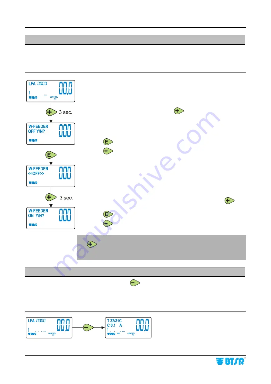
3)  Exclusion and Re-inclusion of a WINDINGFEEDER Device 

When needed, it is possible to temporarily exclude a 

WINDINGFEEDER 

device, 

in order to avoid undesired starts due to vibrations, etc. To exclude and re-include 
a device, operate as follows: 


Exclusion: 


Press and hold down for 3 seconds 

 
The display will show the exclusion confirmation request. 


 to confirm the exclusion. 
 to cancel the operation. 


The <<OFF>> indication, shown on display indicates that the device 
is currently excluded. 


Re-inclusion: 

To re-activate the device press and hold down for 3 seconds 


 to confirm the re-inclusion. 
 to cancel the operation. 


In order to temporarily de-activate a WINDINGFEEDER device simply press 

. The condition of device temporarily de-activated is signaled by the 

lighting the red LEDS inside the 3 push-buttons and inside theTS44 tension 
sensor. 

4)  Control of Temperature and Current Absorbed by WINDINGFEEDER 

At any time, pressing the 


button, you can check the internal temperature (T) 

of the control board (32°C in the example below) and of the motor (31°C in the 
example below), as well as the current absorbed by the motor (C) in Ampere (0.1 A 
in the example below).  


Содержание WINDINGFEEDER

Страница 1: ...WINDINGFEEDER YARN CONTROL SYSTEM Operating Manual ENGLISH Rev 2 0 March 2011 ...

Страница 2: ... without notice For any technical or commercial problem please contact your local BTSR dealer or call directly BTSR customer service centre We will be glad to meet your needs Thank you for your trust and good job The product described herein is compliant with the requirements of EMC 2004 108 EC All BTSR products are covered by patents and adopt exclusive profitable and high tech Solutions WindowsT...

Страница 3: ...nnection 2 4 D WINDINGFEEDER overall dimensions in mm 2 5 Instructions for Correct Yarn Threading 2 7 Chapter 3 OPERATION Operating Characteristics of WINDINGFEEDER Devices 3 1 Symbols shown on LCD 3 2 Functions Directly Available to the Textile Machine Operator 3 3 1 Alarm Reset 3 3 2 Current Yarn Type and Application Reading 3 3 3 Exclusion and Re inclusion of a WINDINGFEEDER Device 3 4 4 Contro...

Страница 4: ...Table of Contents ii WINDINGFEEDER Page intentionally left blank ...

Страница 5: ... is subject to change due to environment conditions such as humidity temperature etc or when the yarn packages are gradually emptying during the normal working process The WINDINGFEEDER devices are fully programmable and can easily be adapted to any kind of yarn or tension adjustment and to any operating speed of the textile machine on which they are installed Furthermore these devices are manufac...

Страница 6: ...guide to solving the main failures of WINDINGFEEDER devices Symbols used Highlights notes warnings and subjects to which the attention of the reader should be directed Indicates a particularly sensitive situation which could have an effect on the safety or proper operation of the system TENSION ERROR All the items concerning the device programming menus within this manual are always show in CAPITA...

Страница 7: ...C LINK KTF Studio software running under WindowsTM environment you can implement an efficient analysis monitoring system which allows you to find and correct even the minimum critical conditions and behavior differences among the various devices Main Characteristics of WINDINGFEEDER Devices Full Digital Technology The WINDINGFEEDER device is a fully high tech digital instrument that allows setting...

Страница 8: ... quite compact 290 x 86 x 94 mm This permits you to install several devices on the same machine with limited encumbrances The device has been designed bearing in mind not only the technological aspects but also the ergonomic ones Thanks to these characteristics the device can be perfectly fitted within the machine structure without compromising the machine spaces which are usual to the operator Us...

Страница 9: ...to 2 500 m min LFA m min Length of Absorbed Yarn Possibility of using the yarn up to the complete package emptying Better machine efficiency Possibility of finding the best application conditions of WINDINGFEEDER device No of coils to be wound around the roller ideal programming values for parameters etc thanks to the continuous visualization in graphic form of both average and peak values of yarn...

Страница 10: ...r an easy subsequent recall Without the need of setting up new parameters these will simply be called from the Data Base and subsequently transferred to the WINDINGFEEDER devices installed on textile machine Possibility of using the TARGET function meter count and the Stop output when reaching the amount of meters setup with possible automatic bobbin change enabling autodoffing Possibility of cont...

Страница 11: ...king parameters of WINDINGFEEDERs to your specific application requirements Possibility of displaying and or printing several graphics showing the real time dynamic variation of the significant operative items such as yarn tension current absorbed by the motor motor torque etc this allows you to speed up and optimize the tuning of the whole system Possibility of updating the WINDFEEDERs software w...

Страница 12: ...c showing the dynamic progress of yarn tension on devices 1 and 2 plus real time display of speed torque current and temperature values PC Link KTF Example of graphic showing the dynamic progress of yarn tension motor torque and current absorbed by device 1 ...

Страница 13: ...Overview WEENDINGFEEDER 1 7 PC Link KTF Examples of WINDINGFEEDER device operation parameters programming ...

Страница 14: ... make easier the tuning of control parameters to the production managers Possibility of displaying in real time up to 4 control graphics related to as many WINDINGFEEDER devices Possibility of displaying saving and printing for each graphic up to 7 different control parameters work tension min max tension motor torque motor speed inlet tension Possibility of immediately checking the efficiency deg...

Страница 15: ...e 0 95 full scale Max applicable tension 10 times the full scale value IS3x TS Sensor Power supply voltage 12 24 Vdc 20 Absorption 15 mA max 20 mA STOP output NPN STOP output protection Protection against over voltages short circuits Maximum Current of STOP output 200 mA continuous 500 mA peack Reaction Delay Programmable from 5 to 1 000 msec Sensitivity Programmable 10 levels Signaling With integ...

Страница 16: ...85 C LCD graphic display 80 x 40 mm Integrated Touch pad 6 buttons rotary selector Protection 2 fuses 1 5A Electrical Interface of WINDINGFEEDER Devices TS44 Connector for TS44 tension sensor connection SM IN SN OUT Connectors for WINDINGFEEDER device daisy chain connection Ext Connector available for future expansions UNICO Connector for intelligent accessory connection IS3 Connector for IS3 yarn...

Страница 17: ...OP2 It is activated when the Windingfeeder device reaches the target For more details about P1 e P2 tensions please refer to chapter 3 Operation Both Inputs and Outputs can be programmed as normally open NO or normally closed NC contacts The programming is global i e every input and every output in the same way operates as NO or NC depending on the selected option For more details please refer to ...

Страница 18: ...chnical Data and Installation 2 4 WINDINGFEEDER PC WINDINGFEEDER Connection Concerning all electrical systems it is a suggested rule to ensure that the ground cable GND is connected to the device support ...

Страница 19: ...Technical Data and Installation WINDINGFEEDER 2 5 WINDINGFEEDER overall dimensions in mm ...

Страница 20: ...tion adjustment C Allen screw for ceramic element eccentric support adjustment TS44 xxxyRW Tension Sensor A Fastening hole with M4 x 20 screw B Loading cell tension sensor Note the TS44 device may automatically carry out the offset function upon special command issued by WINDINGFEEDER device see OFFSET AUTO parameter on P3 programming level A B C TS44 ...

Страница 21: ...et the yarn over the loading cell of TS44 sensor and thread it out of the upper buckle For correct separation of yarn coils on the coil separation element slightly tilt the separation device while the WINDINGFEEDER is running turning the adjustment screw To adjust the yarn brake pressure set the adjustment wheel Push the adjustment wheel towards the yarn brake to increase the braking effect Move a...

Страница 22: ...Technical Data and Installation 2 8 WINDINGFEEDER Page intentionally left blank ...

Страница 23: ...g the programming phase press it to confirm the displayed parameter Pressing and holding down this push button for about 3 seconds on particular parameters you will have the possibility to enable disable the corresponding function 2 PUSH BUTTON RESET Press this push button to cancel possible error signaling on WINDINGFEEDER display red LED flashing During the Programming phase press it to decrease...

Страница 24: ... LCD A Area Etichette OK Indicates the activation of any of the 3 push buttons of WINDINGFEEDER device COM Communication in progress with SMART MATRIX FEEDER terminal or with the PC CONTROL Indicates that the WINDINGFEEDER device is operating in Control status PROGRAM Indicates that the WINDINGFEEDER device is in Parameters Programming status TARGET Indicates that the set Target has been reached I...

Страница 25: ...tion reading 3 Exclusion and re inclusion of a WINDINGFEEDER device 4 Real time control of device temperature and current absorbed by the device s motor 1 Alarm Reset When a WINDINGFEEDER device detects an Error condition E2 Tension Error etc the device stops and the LFA nnnn indication on display is replaced by the error message To reset the alarm once you have removed the cause that generated th...

Страница 26: ... is currently excluded Re inclusion To re activate the device press and hold down for 3 seconds to confirm the re inclusion to cancel the operation In order to temporarily de activate a WINDINGFEEDER device simply press The condition of device temporarily de activated is signaled by the lighting the red LEDS inside the 3 push buttons and inside theTS44 tension sensor 4 Control of Temperature and C...

Страница 27: ...rmware version will temporarily appear on the display To switch from SIMPLE to ADVANCED and viceversa press and hold down for 3 seconds the ENTER button To avoid undesired changes of operating parameters after the installation of WINDINGFEEDER devices and after having setup and checked all the working parameters in ADVANCED programming environment it is advisable to activate the SIMPLE programming...

Страница 28: ...or management of elastic yarns OFFSET Possibility of reading setting the OFFSET value as well as enabling the device Auto Offset function ACCESS CODE Possibility of setting a protection password to prevent undesired access to the device programmable functions U FEEDER CODE Possibility of visualizing and or directly setting the device identification code LANGUAGE Possibility of choosing the languag...

Страница 29: ...thin the P4 level the following parameter can be programmed MOTOR ROTATION DIRECTION SENSOR TYPE BAUDRATE APPLICATION REWIND 1 2 WARP 1 2 YARN TYPE ALL YARN OR ELASTIC LANGUAGE SELECTION USE OF INTELLIGENT TENSION CONTROL ACCESSORY Press the Control button to switch from one programming level to the next one Press Reset button to quit the programming environment ...

Страница 30: ...m of P1 P4 Advanced Programming Levels and Default Settings NOTES The values shown refer to the default parameters set by BTSR A LFA Length of Absorbed Yarn in m min B The selectable languages are Italian English French Spanish German Japanese ...

Страница 31: ... 2 99 5 grams Choose the desired value using to increase the value or to decrease the value to confirm P1 2 ERROR TENSION Tolerance band beyond which the machine will be stopped The error indication and machine stop occur only if such tolerance is exceeded for the time period set in the next parameter TIME ALARM Allowed values 0 0 99 5 grams with automatic limitation to 0 4 grams for what concerns...

Страница 32: ...Operation 3 10 WINDINGFEEDER Example 1 Main Tension 20 g Error Tension 5 g Example 2 Main Tension 50 g Error Tension 20 g Example 3 Main Tension 5 0 g Error Tension 6 g ...

Страница 33: ...is means that the system will automatically calculate the best alarm generation and machine stop time depending on the feeding speed At low speed such time is 500 ms as the speed increases it will be reduced up to a minimum of 50 ms this allows a quick machine stop during normal operation avoiding however the risk of false stops when working at low speed Choose the desired value using to increase ...

Страница 34: ...the function press and hold down for 3 seconds the Enter button The OFF indication means that the function has been disabled In this case the EXIT TENSION parameter will assume the same value set on MAIN TENSION parameter within the P1 programming level To re enable this function press and hold down for 3 seconds the Enter button The OFF indication will disappear and it will be replaced by a modif...

Страница 35: ...n in such a way as to avoid excessive yarn relaxations Allowed values 1 250 The RAMP DOWN t is calculated using a reference table that determines an increase of the ramp time depending on the programmed value 1 very fast ramp time 1ms 250 very slow ramp time 250 msec See the following examples where N value programmed with parameter P2 3 Ramp Down T1 final tension value low T2 initial tension valu...

Страница 36: ...4 K PID This parameter represents a multiplier that affects the control algorithm depending on the yarn elasticity characteristics Allowed values 1 5 1 Rigid Yarn 5 Elastic Yarn Choose the desired value using to increase the value or to decrease the value to return to the beginning of P2 menu to switch to P3 menu to return to CONTROL status without programming P3 and P4 menus ...

Страница 37: ...OFFSET value If the two values are different press briefly to align them You may either enable or disable the Automatic Offset function keeping pressed for 3 seconds If the function is disabled then AUTO does not appear on the display If it is enabled then at every machine stop the device loosens the yarn until this is completely relaxed and it carries out an automatic correction of the Offset val...

Страница 38: ...s currently disabled If you specify an access code this will be requested each time you attempt to activate the programming environment When the CODE request appears type the secret key code using and buttons increase the value of secret key code decreases the value of secret key code Press to save the key code and move to the next parameter P3 4 FEEDER CODE This function allows you to visualize a...

Страница 39: ... Input and Stop signals Normally Open or Normally Closed contact 8 Automatic detection of the optional intelligent accessory to select the P4 level to continue P4 1 MOTOR D This function allows you to choose the rotation direction of yarn feeding motor CW Clockwise CCW Counter Clockwise To move from CW value Clockwise to CCW value Counter Clockwise or vice versa press and hold down for 3 seconds t...

Страница 40: ...e to the next parameter The ELASTIC mode allows a better handling of bare elastic yarns P4 6 LANGUAGE SELECTION This function allows you to select the language used to display menu items messages and errors or to scroll forward backward the list of available languages ITALIANO ENGLISH FRANCAIS ESPANOL DEUTSCH JAPANESE to confirm the language indicated on display and return to the beginning of P4 m...

Страница 41: ... and OFF to confirm and return to P4 menu to return to CONTROL status Management of Tension Error Alarm EXAMPLE The WINDINGFEEDER generates the Error Tension Alarm when the tension goes out of the programmed tolerance band and automatically resets the alarm as soon as the tension returns within the programmed tolerance band Error Tension Alarm active only when the WINDINGFEEDER device operates wit...

Страница 42: ...Operation 3 20 WINDINGFEEDER Page intentionally left blank ...

Страница 43: ...GREEN RED ALTERNATE FLASHING MOTOR LOCKED with CONTROL button ON ON TENSION ERROR BLINKING GREEN RED ALTERNATE FLASHING This condition is obtained when you are working with the tension defined in P2 If you are working with the tension defined in P1 even if you press the Control button the LEDs remain off However pressing the Control button the tension defined in P1 will be displayed To interpret t...

Страница 44: ...vice out of adjustment 1 Clean the loading cell of TS44 sensor using a light air blow max 1 bar 2 Perform a correct adjustment of the OFFSET value on WINDINGFEEDER device as described on page 3 15 ES ES CONT displayed on WINDINGFEEDER display 1 Internal protection against overcurrents 1 Reset the alarm if the problem persists contact your BTSR reseller MT BUS displayed on WINDINGFEEDER display 1 S...

Страница 45: ...FEEDER STOP output press the Control button and confirm the lighting of red LEDs if this does not occur please contact your BTSR reseller it could be necessary to send the device to the BTSR repair centre The WINDINGFEEDER device does not communicate with SMART MATRIX FEEDER terminal 1 The identification code of WINDINGFEEDER device is not correct 2 Failure on SMART MATRIX FEEDER terminal 3 Wiring...

Страница 46: ...ed LEDs and of TS44 sensor At the end of the operation press again the button and make sure that all the red LEDs turn off If the fault is not included in the above table please contact your local BTSR reseller giving a detailed description of the kind of fault and the conditions in which it occurred Should be necessary to call the BTSR Technical Service Department read the code printed on the fau...

Страница 47: ...BTSR International S p A Via S Rita 21057 OLGIATE OLONA VA Phone 0331 323202 Fax 0331 323282 Internet www btsr com REV 3 0 03 11 DISTRIBUTOR ...

Отзывы: