Commissioning
B 3
ekrPro Com
60
web guide controller
EDV No.:
MD.191.01.05/1.6.x Chapter:
B 3
with analog sensors
Date:
23.11.2007
Page:
30/73
Digital blocking output (oil blocking)
If a hydraulic actuator is used, then a blocking valve can be
connected to terminal 67 (X15), in order to interrupt the oil flow.
Oil blocking is only active with a hydraulic actuator and when one of
the following conditions is fulfilled:
•
Man output = 0 and position controller deactivated.
•
A limit switch position is reached.
•
An over-temperature and a short circuit exist.
•
Missing enable for the actuator:
(see actuator enable terminal 53)
Behaviour when oil blocking is switched on:
•
PWM and analogue output are blocked.
•
Blocking is activated after a 150 ms delay
(OV at terminal 67 (X15)
Behaviour when oil blocking is switched off:
•
Blocking is deactivated
(24 V DC at terminal 67 (X15))
•
Blocking is deactivated after a 150 ms delay.
B 3.7.5.2.3 Direction – setting the
actuator guiding direction
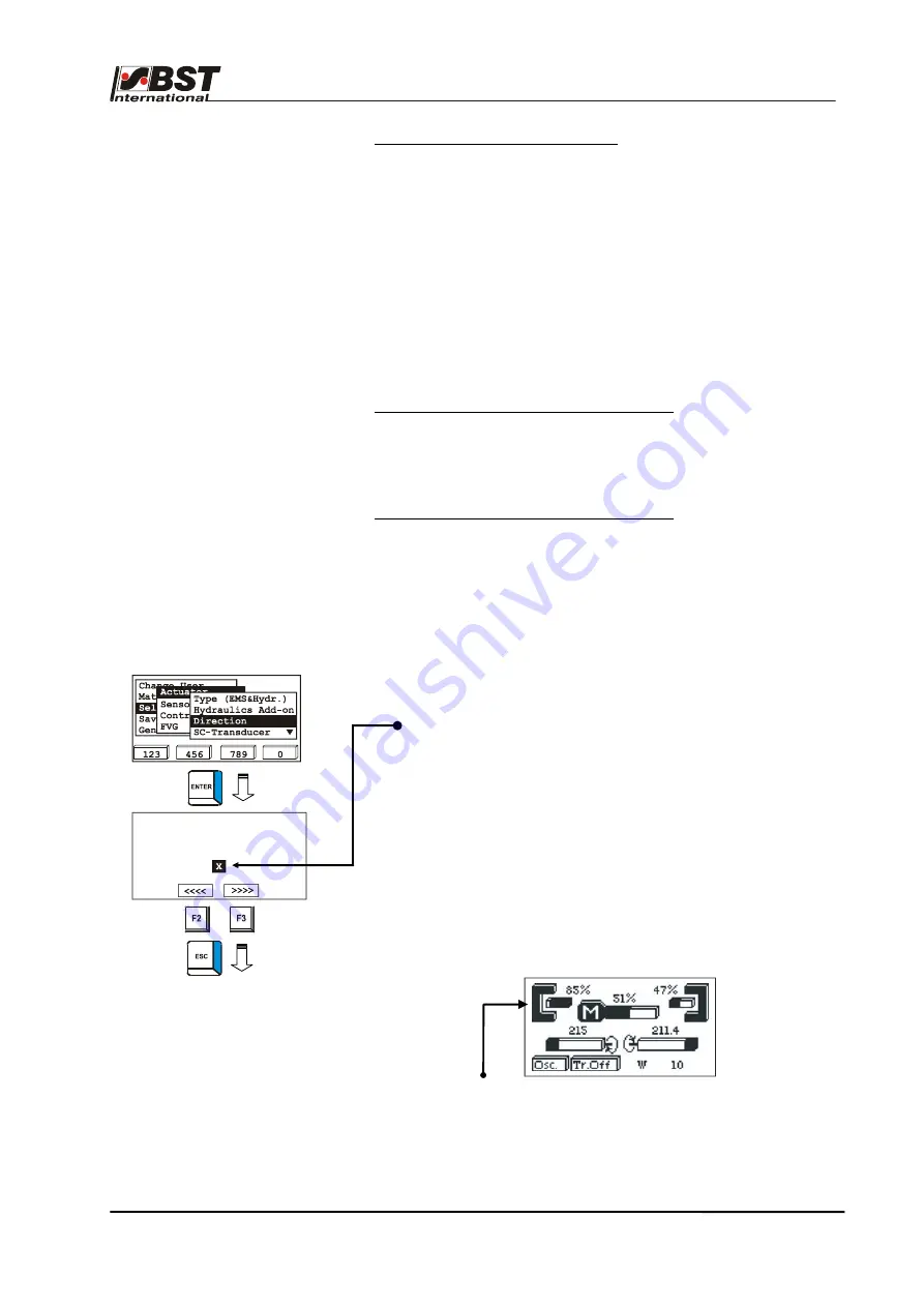
1. Select the sub-directory
Direction
from the menu
Actuator
.
Confirm the selection by pressing ENTER.
If necessary, the actuator guiding direction for manual mode
can be reversed by activating the checkbox
Mot. Dir.
Inverted
.
The rotational direction can be checked on the spot.
Drive the actuator using the
F2
or
F3
key.
If key
F2
is pressed, the actuator must move the material web
in the direction of sensor 1, if
F3
is pressed it must move it
towards sensor 2!
Pressing
F2
or
F3
automatically changes the controller to
manual
operating mode.
The sensor allocation can be checked on the spot. Press the
MENU
button. The operating display is shown.
Cover a sensor. The change to the coverage range shows the
allocation.
After this, press the menu key to ENTER to the settings menu.
2. Press the
ESC
button to exit the window.
Toggle Man Dir. until
F2 moves to sensor 1
Mot. Dir. Inverted


