background image


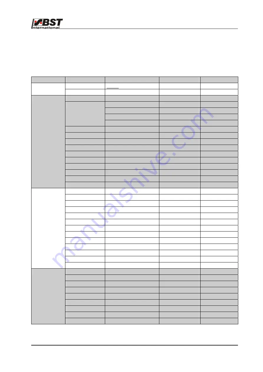
Default settings 

D 2


ekrPro Com

60 

web guide controller 

EDV-No.: 

MD.191.01.05/1.6.x Chapter: 

D2 


with analog sensors 

Date: 

23.11.2007 

Page: 

1/6 

Appendix D 2 Default settings 

The default settings have been set up in the controller in the 
factory. The following settings are set up again after a reset has 
been carried out: 
 

Menu 

Parameter Level 1  Parameter Level 2 

Parameter Level 3  Default Value 

User Level 

Active user level 


 Admin. 

Change User 

Password 


 2 

Type (EMS&Hydr.)   


 EMS 

17 

Zero elevation [%] 


 0 

Dither amplitude [mA] 


 0 

Use teach table 


 off 

Hydraulics Add-on 

Specific current control 


 off 

Direction 


Dir. inverted 

 off 

SC Transducer 

Type & Dir. 

Type 

 EMS 

Pot. 


Inversion 

 off 


Pos. Limit 

active 

 off 


Limit left 

 -2048 


Limit right 

 +2047 


SC W & XP 

Setpoint 

 0 


Gain 

 20.00 

Man Pos. Control 


 off 

Actuator 

Man Speed 

[1/1000] 


 700 

Sensor 1 


 IR2005 


Dark  

-2048 


Bright  

+2047 


Inv.  

Off 

Sensor 2 


 IR2005 


Dark  

-2048 


Bright  

+2047 


Inv.  

avtive 

Sensor 3 


not connected 


Dark  

-2048 


Bright  

+2047 


Inv.  

off 

Sensors/EFE 

EFE Remote Adj. 

Choose EFE if present 


not connected 

Gain & Offset 

Edge 1 

 0 


xp 

 5.00 


Edge 2 

 0 


xp 

 5.00 


Center 1&2 

 0 


xp 

 5.00 


Edge 3 

 0 


xp 

 5.00 

Control loop 

Speed control 


 active 

Содержание ekrPro Com60

Страница 1: ...191 01 05 1 6 x with analog sensors Date 23 11 2007 BST Web Guiding System ekrPro Com60 with analog sensors BST International GmbH Heidsieker Heide 53 33739 Bielefeld Germany Tel 49 5206 999 0 Fax 49 5206 999 999 e mail info bst international com ...

Страница 2: ...otect yourself as the operator from life threatening injuries caused by electrical voltages Note This symbol is used to point out additional useful tips which will help you to make optimum use of all of the functions Using the keys Using the keys is represented by the following symbols in this manual Press key Key combinations keys have to be pressed simultaneously Press keys in the specified orde...

Страница 3: ...troller EDV No MD 191 01 05 1 6 x with analog sensors Date 23 11 2007 Contents Symbols used in this operating manual Table of contents Section A General information Section B Commissioning Section C Operation Section D Appendix ...

Страница 4: ...guide controller EDV No MD 191 01 05 1 6 x with analog sensors Date 23 11 2007 Section A General information A 1 Description A 2 Specifications A 3 Transport Storage A 4 Decommissioning ekrPro Com60 with analog sensors ...

Страница 5: ...area A1 3 A 1 4 2 Oscillation types and curves A1 4 A 1 4 2 Allocation of FVGs for a FVGPro 2MK A1 4 A 1 5 Connectable components A1 4 A 1 6 Safety information A1 5 A 1 7 Emissions A1 5 A 2 Specifications A2 1 A 2 1 ekrPro Com60 controller version XT A2 1 A 2 2 Optical edge sensor IR2001 IR2005 A2 3 A 2 3 Optical edge sensor IR2002 A2 3 A 2 4 IRS U 2 A opto electronic analog sensor A2 3 A 2 5 Ultr...

Страница 6: ...n be interconnected at different levels into a system network via a CAN Bus A 1 2 Utilisation The ekrPro Com60 is a microprocessor controlled web guiding controller Together with other BST components it may be used for Web edge guiding right or left Web center guiding Guiding on continuous or interrupted printed lines Guiding on continuous or interrupted printed edges still being prepared Web widt...

Страница 7: ...g link applies SENSOR LEFT Sensor 1 SENSOR RIGHT Sensor 2 The following is valid in respect of the sensor mounting positions The sensor which is located to the left of the material in the web movement direction when looking from the material top side is sensor 1 The material top side is the side of the material web which is not in direct contact with the deflection pulleys of the pivoting frame Ex...

Страница 8: ... see section B 3 4 4 3 1 When the control units is delivered inversion of the sensor signal for sensor 2 is activated factory setting A 1 4 3 Size of oscillation amplitude related to sensor scanning area The maximum possible oscillation amplitude is 80 of the sensor visual range As an example the oscillating web position is shown herewith an attitude of 40 in Sensor oscillation mode Sensor left No...

Страница 9: ...tion the curve described is a delta function The FVG oscillation describes a curve in accordance with a sine function Selections and settings are described under Point B 3 7 5 8 2 A 1 4 5 Allocation of FVGs for a FVGPro 2MK A 1 5 Connectable components The general plan annex C2 shows the components that can be connected to the ekrPro Com60 controller FVG 1 FVG 2 Web travel direction internal limit...

Страница 10: ...mitted to undertake the assembly installation and commissioning Before starting work ensure the equipment is electrically isolated To this end always carry out the following measures 1 Switch off 2 Prevent switching back on 3 Check the equipment is isolated 4 Earth 5 Cover or shield any adjacent parts that are still live The mains power must always be switched off before the equipment is opened If...

Страница 11: ... 4 V low and 8 V high but can only be used against switched sensors pnp supply 24V DC Digital inputs 12x digital inputs no metallic separation input resistor 4 7 KΩ operating points 4 V low and 8 V high but can only be used against switched sensors pnp supply 24V DC Power supply outputs 2 x 24V for CCD Pro camera Controller outputs Controller outputs 10 3V to 10 V 12 bit 1x analog output 10 V to 1...

Страница 12: ...graphics module with 128 x 64 pixel and LED background illumination Ambient conditions Temperature 0 to 45 C max Humidity 5 90 no condensation Weight ekrPro Com60 approx 2 1 kg ekrPro Com60 Desk approx 2 3 kg Case dimensions ekrPro Com60 Mounting unit Installation ekrPro Com60 Desk Built in unit 240 225 140 125 max 10 15 115 105 205 140 160 240 70 ...

Страница 13: ...4 Ambient conditions Temperature 0 to a max 45 C Humidity 5 90 no condensation Case dimensions standard version W 40 mm H 95 mm D 107 mm A 2 3 Optical edge sensor IR 2002 Power supplies from the controller Measuring range typical 8 mm Visual range typical 13 mm Output analog Protection class IP 54 Ambient conditions Temperature 0 to 45 C max Humidity 5 90 no condensation Case dimensions standard v...

Страница 14: ...mperature 0 to a max 45 C Humidity 5 90 no condensation Case dimensions standard version B 25 mm H 76 mm D 113 mm A 2 6 Reflection button TW 54 C5 Power supplies 8V 15V from the controller Lamp voltage 5V 0 8A from the controller for maximum of one sensor Measuring range 5 0 mm at 6 mm sensing distance 2 5 mm at 13 mm sensing distance Output signal Negative with black areas Positive with white are...

Страница 15: ... B 67 mm H 105 mm D 128 mm A 2 8 Reflected light measuring light barrier R 42 D etc R 42 D 12 R 42 D 16 Power supplies 12V 12 mA or 12V 15 mA or 15V 20 mA Lamp voltage 5V 4W from the controller for a maximum of one sensor Max distance 1 m 2 m Measuring range in front of front lens 15 mm 40 mm Diameter of light beam in front of front lens 25 mm 55 mm Diameter of light beam at half distance 40 mm 55...

Страница 16: ... 2007 Page 6 7 A 2 9 Fork light barrier G 53 C2 5 Power supplies from the controller Lamp voltage 5V Fork width 29 mm Measuring range 3 5 mm Diameter of light beam 11 mm Protection class IP 65 Ambient conditions Temperature 20 to a max 60 C Humidity 5 90 no condensation Weight 400 g Case dimensions B 21 mm H 85 mm D 87 mm ...

Страница 17: ... be able to quickly charge 5 sec the input capacitance approx 950µF of the control amplifier after switching on without recognizing this as a short circuit and so switching off again The output should be permanently resistant to short circuiting overloading and idle running 2 Separate power pack If a separate power pack is used for the BST components we recommend the use of units manufactured by P...

Страница 18: ...sport The equipment will be shipped in accordance with the details stipulated in the order completely assembled and interconnected to the web guide control system as component parts in standard cardboard boxes with cellular lining material If the unit will not be incorporated immediately it should be stored in a dry room until installation ...

Страница 19: ...ether with the entire machine The necessary procedures must be prepared by the manufacturer of the machine You must take into consideration that the control system is generally considered to be an electrical electronic device which must be disposed of in accordance with the current legal requirements You might also be able to return the system to BST International GmbH but the corresponding agreem...

Страница 20: ... controller EDV No MD 191 01 05 1 6 x with analog sensors Date 23 11 2007 Section B Commissioning B 1 Installation B 2 Controls B 3 Commissioning B 4 Terminal assignments and service displays ekrPro Com60 with analog sensors ...

Страница 21: ... B 2 1 Control panel B2 1 B 2 2 Navigating within the system B2 2 B 2 2 1 Function keys F keys B2 2 B 2 2 2 Arrow keys B2 5 B 2 2 3 Buttons B2 6 B 3 Commissioning B3 1 B 3 1 General information B3 1 B 3 2 Electrical connections B3 2 B 3 3 Commissioning with a CAN bus B3 3 B 3 3 1 Check unit address or set up if necessary B3 3 B 3 3 2 Terminator activation B3 5 B 3 4 Adjust password B3 7 B 3 5 Comm...

Страница 22: ... 35 B 3 6 4 4 Control Loop Control loop settings B3 37 B 3 6 4 5 FVG Sensor positioning device B3 38 B 3 6 4 6 Width Measure Web width measurement B3 50 B 3 6 4 7 Edge Sources Assignment of the sensors B3 54 to the guiding modes B 3 6 4 8 Add Functions Special functions B3 56 B 3 6 4 9 Dig IO Config Configuration of the digital B3 60 inputs and outputs B 3 6 4 10 Special Special device settings B3...

Страница 23: ...perature 0 to a max 45 C Humidity 5 90 no condensation B 1 2 Installation ekrPro Com60 mounting unit B 1 2 1 Securing hole diagram B 1 2 2 Installation 1 Drill the securing holes as shown in the mounting plan 2 Use the four securing screws to attach the housing 3 Wire in the electric cables if required or plug in the necessary cable connections Attention A free area of at least 300 mm in front of ...

Страница 24: ...nalog sensors Date 23 11 2007 Page 2 7 B 1 3 Installation ekrPro Com60 Desk built in unit B 1 3 1 Installation dimensions B 1 3 2 Cabling Attention A space of at least 140 mm must be guaranteed for the cabling in order to ensure that the cables are laid correctly see illustration Section min 140 ...

Страница 25: ... drill four mounting holes installation dimensions see chapter B 1 3 1 2 Slide the ekrPro Com60 Desk into the recess 3 Use the four securing screws to secure the controller ekrPro Com60 Desk in place 4 Wire in the electric cables or plug in the necessary cable connections Attention A free area of at least 300 mm in front of the housing must be guaranteed so that it can be opened max 10 ...

Страница 26: ... glands 2 Pull out the clamping insert from the intermediate supports Attention Do not press down on the cable insert 3 Strip cable back by 8 mm so that the screen braiding is uncovered 4 Pull the union nut onto the cable 5 Feed the cable into the cable clamp and bend the screening back over the cable clamp 6 Push the clamping insert to the intermediate support 7 Fit the screws Union nut Cable ins...

Страница 27: ...nged as follows in order to ensure clear allocation of the two keys on the front foil of the controller to the corresponding contrast transitions The sensor connection cable points in the direction of sensor 1 This sensor arrangement results in the following key allocation Contrast transition BRIGHT DARK Contrast transition DARK BRIGHT TW 54 C 5 T 62 D 1 Connection cable Material web Sensor 1 Sens...

Страница 28: ...ction roller This will ensure that any material web height fluctuations are eliminated at the scanning point The distance between the sensor scanning optics and the material web must be set so that there is a light spot with a diameter of approximately 8 mm corresponding to a scanning distance of approximately 17 mm on the web We recommend that the sensor angle is reduced by 5 15 in the web runnin...

Страница 29: ...d out on a deflection roller This will ensure that any material web height fluctuations are eliminated at the scanning point The distance between the sensor scanning optics and the material web has to be 6 12 mm depending on the required measuring range diameter of the light spot The measuring range light spot diameter depends on the distance between the contrast transitions Only one contrast tran...

Страница 30: ...perating hours parameters and the set up menus Keypad The controller can be configured for operation using this keypad Key Function Automatic guiding Manual positioning Centring the guiding device servo center Left web edge guide Right web edge guide Web center guiding Edge contrast control Contrast transition light dark Edge contrast control Contrast transition dark light Automatic operating mode...

Страница 31: ...al functions e g oscillation not used at the present moment Menu selection B 2 2 Navigating within the system Use the arrow keys and the F1 F4 function keys to navigate within the system The different functions are explained in the following If incorrect entries are made or if functions are active which for example prevent entering of parameters e g keyboard lock the appropriate message windows ar...

Страница 32: ...row keys to navigate to the required menu sub option or it can be selected directly by using the shortcut number instead For example Selecting the actuator The associated menu sub option is 611 see navigation overview as well 1 Press key This will display the set up menu To enter the shortcut number 2 Press F2 key 3x 6 The General setup menu including the first Actuator submenu is called up 3 Pres...

Страница 33: ...an entry being made 4 Now enter the next number in the same way as described above in Section 3 5 Press the ENTER button to import the modified value 6 Press the ESC button to cancel the value Editing box The arrow keys can also be used to enter a value in the editing box in addition to using the F keys Use the horizontal arrow keys to position the cursor on the number to be modified Now use the v...

Страница 34: ...the required control if there are several control elements displayed in the same dialog window For example Use the right arrow key to scroll forward and use the left arrow key to scroll backwards The vertical arrow keys do not have a function here Option lists An entry from a default list can be selected from an option list This is realised by pressing the ENTER button to open the selected option ...

Страница 35: ...onents e g stop switch statuses Example B 2 2 3 Buttons Button control elements are present in certain dialog windows If a button is marked and the ENTER button is pressed afterwards an action will be executed e g traversing the actuator The button will be displayed as being pressed down and the action will continue to be executed all the time that the ENTER button is kept pressed down activated n...

Страница 36: ...stem configuration is required if components or the controller have been exchanged on site The range of the settings and therefore the set up menus that have to be taken into consideration depend on the system being used To simplify commissioning the commissioning staff can select his system from a list of the most common standard systems see chapter B 3 5 Following the selection all of the basic ...

Страница 37: ...he conductor and the wiring sleeve Using cable without wiring sleeves For fine and multi core cable and for fine wired cable whose kink resistance is not sufficient due to its small diameter in order to overcome the contact force of the clamping springs the clamp must be correctly opened using a screwdriver Check that all the cables are fitted tightly after the connections have been made in both c...

Страница 38: ...Com60 address is preset to 1 in the factory delivery state Set the S1 BCD switch to 1 if the ekrPro Com60 is the only device connected to the CAN bus If you want to run several ekrPro family devices on one CAN bus system then different device addresses 1 8 must be set for the devices One of the devices must be set to device address 1 without fail Device addresses 0 and 9 are reserved Each device a...

Страница 39: ...ug 3 Check setting of BCD switch S1 If necessary set device address to S1 1 4 Refit the plug 5 Restore the power FVGPro Module if fitted FVGPro Module The device address setting up is also crried out via the S1 BCD switch mounted on the board Procedure 1 Switch off the power to the FVG Pro module 2 Open housing s front cover 3 Check the setting of the BCD switch S1 If necessary set device address ...

Страница 40: ...below B 3 3 2 1 ekrPro Com60 In the ekrPro Com60 the activation is carried out using switch S3 on the processor circuit board Set the switch to ON Procedure 1 Switch off the power to the controller 2 Open controller s front cover 3 Activate terminator S3 switch position ON 4 Close the controller s front cover 5 Restore the power B 3 3 2 2 ekrPro Key60 if fitted In the ekrPro Key60 activation is ca...

Страница 41: ...n takes place using the DIP switch segment 1 S1 ON for the CAN 1 B 3 3 2 4 FVGPro Module if fitted In the FVGPro Module activation is carried out via switch S3 on the processor circuit board Set the switch to ON Procedure 1 Switch off the power to the module 2 Open module s front cover 3 Activate terminator S3 switch position ON 4 Close the module s front cover 5 Restore the power Switch S3 CAN 2 ...

Страница 42: ...ses The unit is supplied with the user level Admin set The indicated default password should only be used for the first access to the setup menu and then an application appropriate password entered This is also true for the Mainten user level This protects the system against unauthorized access Make sure these new passwords are only known to the authorized personnel BST International GmbH is not l...

Страница 43: ...R 3 Use the right and left arrow keys to select the Password editing box and press ENTER Enter the password and confirm the entry with ENTER 4 Press the F3 key login The controller changes to the selected user level The Setup menu selection window appears Entries for which there are no user rights in the selected user level are shown greyed out Enter user level password User level Mainten Password...

Страница 44: ...elect menu Sel Std System and press ENTER 3 The selection window for the standard system will appear 4 Press the ENTER button The option list opens with the most common standard systems Individual entries each contain the following information 5 Use the vertical arrow keys to select the system that matches the present system Confirm the selection with the ENTER key The selected system is displayed...

Страница 45: ... differs from the BST setting see chapter A 1 4 or if the sensor outputs an inverted signal e g another manufacturer s sensor is being used then the checkbox Inv must be checked A master set up will be carried out afterwards Master set up can be run automatically or manually 3 Automatic master set up Press the F1 button and then cover the sensor s scanning window with an opaque material for two se...

Страница 46: ...ws the allocation After this press the MENU key to ENTER to the settings menu 2 Press the ESC button to exit the window B 3 5 4 Setting the actuator path limits From here it is possible to limit the adjustment travel of the actuator 1 Select Actuator in General Setup then the sub directory SC Component and finally Pos Limit Confirm the respective selection by pressing ENTER 2 Use the vertical arro...

Страница 47: ...d gain for SC operating mode From here the centre position and the amplification for operating mode SC are set 1 Select Actuator in General Setup then the sub directory SC Component and finally SC W XP 2 Press ENTER to open the inputting menu and enter the parameters 3 The current actuator position will be displayed in the field mot pos 4 Use the F2 and F3 keys in MAN operating mode to traverse th...

Страница 48: ...orption in the case of ultrasonic sensors The material set up is the same for all three sensors The procedure for sensor 1 is used as the example here 1 Press the MENU button to open the set up menu 2 Select Material set up and confirm by pressing ENTER 3 Select Sensor 1 and confirm by pressing ENTER This will open the Sensor 1 material set up window Material set up can now be carried out either a...

Страница 49: ...letes the material set up for this sensor Material set up is finished when the same procedure has been carried out for any other sensors connected to the controller B 3 5 6 2 Manual material set up 1 Completely cover the sensor s scanning window with the material to be scanned 2 Press the F3 key 3 Completely remove the material from the sensor scanning window no material over the sensor 4 Press th...

Страница 50: ...3 5 7 1 Default values set Depending on the configuration selected under Select Standard System various default settings are carried out in the FVG submenu B 3 5 7 1 1 Configuration dependent default values 1 Selection IR2005 EMS 17 or US2007 EMS 17 For this selection the sensor positioning device connection entitled not connected is selected and entered No additional entries have to be carried ou...

Страница 51: ...se configurations is selected the FVG 2MK Op sensor positioning device connection is selected and entered The following settings dependent parameters are selected and entered for the FVG 1 Slide 1 and the FVG 2 Slide 2 Slide 1 Homing Direction retraction direction and limit switch assignment at the first setting after switching on not reversed Offset positional offset to FVG position at the first ...

Страница 52: ... FVG 2MK60 20088 for FVG 2MK75 61666 The manufacturer has entered this default setting and you are only permitted to modify it if necessary after having obtained the manufacturer s agreement The relevant procedure then has to be agreed All warranty claims will be invalidated in any other case B 3 5 7 1 2 Configuration independent default value The following values are general settings which can be...

Страница 53: ...ion This functionality is only effective once pre positioning has been activated Velocities adjustment of positioning speeds at the first setting after switching on Retract velocity 60 mm s Edge push velocity 5 mm s Slow manual velocity 1 mm s Fast manual velocity 60 mm s Norming velocity 60 mm s Special Special settings for driving the FVG slides at the first setting after switching on Mode after...

Страница 54: ...ons 1 With web edge guiding Detection of torn off sections on the web edge using edge sensors IR2001 2005 US2007 This function is activated during web edge guiding if during operation of the web guiding system errors arise from the web edge that is being scanned The function detects both tears into the material web inward tear as well as projecting material outward tear 2 With contrast guiding Gui...

Страница 55: ... directions If the preset maximum permissible rate of change sig chg lim is exceeded then this is recognized as a tear After a preset delay time delay has elapsed the web guiding system is automatically blocked If the set rate of change is undershot then blocking of the guiding system is not lifted Lifting of the blocking is only implemented if the preset threshold value threshold is again undersh...

Страница 56: ... Alignment of the contrast sensor When scanning an interrupted line correct alignment of the contrast sensor must be observed The contrast sensor must be aligned so that the edge of the line is located in the sensor light spot Only one edge may be located within the light spot correct wrong wrong 3 Operating mode setting for the contrast sensor T 62 D 1 The operating mode selection switch on the s...

Страница 57: ...ameters can be set Sensor Selection of the sensor with which tear off detection is to be implemented threshold Percentage covering of the sensor measuring band above which a change is detected as a tear For the example value entered here 80 20 this means that the function detects a tear if more than 80 or less than 20 of the sensor measuring band is covered sig chg limit 4ms Maximum permissible ra...

Страница 58: ...to be displaced within the sensor s visual range using adjustable amplitude size of the lateral displacement and frequencies displacement speed The format of the web displacement when the controller is operated without a sensor positioning device follows a delta curve When operated with a sensor positioning device a sine wave web displacement takes place See also chapter A1 Point A 1 4 4 Oscillati...

Страница 59: ... parameters have the following meanings Amplit Auto Amplitude of the oscillation in operating mode Automatic The percentage value relates to the size of the sensor scanning area Setting range 1 to 99 Amplit SC Setting up the amplitude for the SC operating mode The percentage wise input of the amplitude relates to the distance between the software limit switches One limit switch represents 0 and th...

Страница 60: ...ed start osc after restart When the function is activated the oscillation is immediately started when the system is switched back on B 3 6 Save settings Once the parameters have been determined for the current system they can be saved This enables the facility to access them again at any time in the case that modifications have been carried out unintentionally or by unauthorized persons 1 Press th...

Страница 61: ...aterial set up e g different material transparency at the optical sensors or different sound absorption in the case of ultrasonic sensors The procedure for material setup is described in chapter C 2 3 B 3 7 3 Sel Std System Selection of a standard system To simplify commissioning the commissioning staff can select his own system from a list of the most common standard systems listed under the menu...

Страница 62: ...n aligning the system are contained in the General set up The following procedures are provided for the different operating modes However the default values should be loaded before the special parameters are set up This will meet the condition for a standardised basic output B 3 7 5 1 Setting the default values 1 Go to the General set up menus and then select Sel Std System 2 Press the F1 key The ...

Страница 63: ...p from the sub menu and then press ENTER 2 Select Actuator in General Setup and then select the Type EMS Hydr sub directory afterwards Confirm the respective selection by pressing ENTER 3 The default actuator will be displayed on the screen Press the ENTER button and the actuator option list will then be opened Now use the vertical arrow keys to select the actual actuator that is connected to the ...

Страница 64: ...20 0 No SV 1 10 32 300 mA 20 0 No SV 1 10 48 1000 mA 40 0 No SV 1 6 300 mA 20 0 No HR 024 300 mA 1 No HR 040 300 mA 20 0 No EH St 9 3 300 mA 25 5 No The dither frequency is 50Hz 1 This setting is dependent on the fitted continuously operated valve SV 1 10 x 3 The system must be optimized to the actual settings after the parameters have been entered This is realised by an integrated self teach func...

Страница 65: ...tivated 24 V DC at terminal 67 X15 Blocking is deactivated after a 150 ms delay B 3 7 5 2 3 Direction setting the actuator guiding direction 1 Select the sub directory Direction from the menu Actuator Confirm the selection by pressing ENTER If necessary the actuator guiding direction for manual mode can be reversed by activating the checkbox Mot Dir Inverted The rotational direction can be checked...

Страница 66: ...EMS 20B EMS 21 and EMS 22 there is a common servo center component In this case EMS_Pot has to be selected Select not connected if a servo center component is not connected to the system 4 Confirm the selection by pressing ENTER The screen will ENTER to the previous window 5 Drive the actuator using the F2 key while monitoring the bar indicator in the display Position feedback via the servo center...

Страница 67: ...settings can only be entered in the deactivated state 3 Use the F2 key to drive the actuator until it reaches the required left limit switch position The actual position of the actuator supplied by the position feedback is shown in the middle above the F2 and F3 keys 4 Confirm this position by pressing the F1 key The limit switch position is stored The corresponding position value is shown below t...

Страница 68: ...he sub directory SC Transducer and finally SC W XP 2 Press ENTER to open the inputting menu and enter the parameters 3 The current actuator position will be displayed in the field mot pos 4 Use the F2 and F3 keys in MAN operating mode to move the actuator into the required position 5 Press the F4 key if you want to save the actual position as the set point for the servo center position The setting...

Страница 69: ... vertical arrow keys To test the position controller the actuator can be moved in manual mode to a desired position using the F2 and F3 keys If the position controller is activated the function can be interrupted by pressing the F4 key e g to prevent damage to the material web 4 Press the ESC button to exit the window B 3 7 5 2 6 Man Speed adjustment speed for manual mode This sub menu is used to ...

Страница 70: ...sors EFE in General set up and then select the Sensor 1 sub directory afterwards Confirm the respective selection by pressing ENTER 2 Select the type of sensor that is connected to the system from the option list displayed in the new window that has opened up and then enter it Attention If the mounting position of the selected sensor differs from the BST setting see chapter A 1 4 or if the sensor ...

Страница 71: ...p B 3 7 5 3 2 EFE Remote Adj Commissioning of remote electronic fine adjustment EFE A remote electronic fine adjustment unit is not identified automatically by the controller It must be entered in the set up menu 1 Select Sensors EFE in General Setup and then select the EFE Remote Adj sub directory afterwards Confirm the respective selection by pressing ENTER 2 Not connected is the default factory...

Страница 72: ...9 99 4 Press the ESC button to exit the window after you have entered the settings B 3 7 5 4 2 Adj done Limits Bearing position controlled This function is only relevant when being used together with a Profibus DP module for exchanging data with the customers PLC The corresponding protocol is Protocol 1049 Using the specifications notification threshold evaluations are made in this sub menu as to ...

Страница 73: ...ariations which can be caused by varying loading of the actuator are automatically compensated This activation of this function is a default setting It must be deactivated if a tacho generator is being used 1 Select Speed control in the selection window and then confirm by pressing ENTER 2 Activate speed control using the vertical arrow keys 3 Press the ESC button to exit the window de activate sp...

Страница 74: ... undertaken on the interconnections must only be carried out with the power switched off The FVG function has been set to not activated in the factory i e no further settings are required if an FVG is not connected to the system The required setting must be entered if the FVG function will be used B 3 7 5 5 1 Connection Activating of the sensor positioning device FVG connected 1 Select FVG in Gene...

Страница 75: ...e set up in the next steps 1 Mark Int FVG in the FVG selection window and then confirm by pressing ENTER Select Homing Dir from the sub directory and then press ENTER to open the inputting menu 2 Press the F1 key to check the selected retraction direction By pressing the F1 key the FVG slide must move outwards into the homing position After the homing position is reached the limit switch with the ...

Страница 76: ...current FVG position which results in the Abs slide pos Offset 2 position offset to FVG2 slide position The meaning of the entry and display fields is equivalent to those of Offset 1 2000 mm has been set as the default value for the FVG2 offset When carrying out initial start up this value must be adapted to the actual FVG length If Sensor 2 moves in the opposite direction to Sensor 1 and if the d...

Страница 77: ...the inputting menu after you have entered the settings If material has already been placed in the FVG adjustment range you can also enter the inside limit position directly into the editing box If you are now working with a position offset this does not need to be referred to in this dialog window The following arises from the representation in the operating display Feed Feed for stepping motor ge...

Страница 78: ...and then confirm by pressing ENTER Select Slide 1 and confirm by pressing ENTER 2 Select Homing Dir from the sub directory and then press ENTER to open the inputting menu 3 Press the F1 key to check the selected retraction direction By pressing the F1 key the FVG slide must move outwards into the homing position After the homing position is reached the limit switch with the outer label must be act...

Страница 79: ...the absolute distance to this reference point Abs slide pos The setting up of an absolute reference system is necessary for use of the Pre positioning function Example 1 Press the F1 key The FVG slides move to the home position 2 Measure offset FVG1 distance between reference point Î centre sensor measurement window and enter the value under offset mm 3 Use the F2 and F3 buttons to traverse the FV...

Страница 80: ... directory and then press ENTER to open the inputting menu 2 Press the F1 to start the movement of the slide to the park position home position After this position has been reached the FVG stops 3 Use the F2 or F3 buttons to carefully traverse the sensor in the direction of the inner limit switch Once the limit switch has been reached press key F4 set This completes the adjustment procedure 4 Pres...

Страница 81: ...e from the sub directory and then press ENTER to open the selection menu 2 The following retract modes are available in the selection menu SC The sensor positioning device will traverse into the park position after switching over to the SC mode Man The sensor positioning device will traverse into the park position after switching over to the MAN mode SC Man The sensor positioning device will trave...

Страница 82: ...de is normally used for ultrasonic sensors 3 Press the ESC button to exit the inputting menu after you have made the selection B 3 7 5 5 7 Width Adjust FVG operating mode for center line guiding Use Width Adjust to select FVG operating mode for center line guiding 1 Select Width Adjust from the sub directory and then press ENTER to open the inputting menu 2 The standard values are already entered ...

Страница 83: ... the ESC button to exit the window B 3 7 5 5 8 Repositioning repositioning of the material after certain events The current position of the material web is saved once an event takes place e g web tear Once the event has been rectified the material is repositioned to this position This functionality is only effective once pre positioning has been activated 1 Select Repositioning from the sub menu a...

Страница 84: ...sor positioning device retraction speed Edge push vel mm s This parameter is used to match the traversing speed of the sensor positioning device to the displacement speed of the actuator This prevents the sensor mounted on the FVG slide from being pushed into the more slowly sideways moving material web during edge searching during web centerline guiding Slow Man vel mm s Speed which should be use...

Страница 85: ...can be accepted as is or adapted to the application 3 Press the ESC button to exit the window Mode after Error Operating mode which the system switches to after an error occurs e g web tear Sensor cover guarding This monitoring function prevents destruction of the material web due to unwanted contact with the sensors If the coverage of the sensor scanning area with the checkbox activated exceeds 9...

Страница 86: ...ic operating mode 4 Enter the width under enter ref width after the sensors have reached the edges of the calibration sheet and press the F3 button to take over the entered value 5 The adjustment procedure is finished The actual measured value current width and the entered reference value ref width must both show the same size 6 Press the ESC button to exit the window The reference width value las...

Страница 87: ...e indicated a Material width is in valid range b Material width is too wide when related to the upper warning limit it lies in the W area 24V DC at output 66 c Material width is too small when related to the lower warning limit it lies in the W area 24V DC at output 65 d The material width lies outside the absolute tolerance It lies in the error limit areas E 24 VDC at output 66 e The material wid...

Страница 88: ... 3 7 5 6 3 Opmodes Operating modes in which the width measurement should be active You can use this window to determine in which operating modes the width measurement is able to be implemented This makes it also possible to carry out a web width measurement without an FVG if the checkbox has been activated for the corresponding operating mode If an FVG is connected the condition is that retraction...

Страница 89: ...nfirm by pressing ENTER afterwards 2 A sample type selection window opens The following selection types can be selected Guiding Mode Control input Key Edge 1 Edge 1 Edge 2 Edge 2 Edge 3 Edge 3 contrast transition Src SC Centre position control encoder Src EFE Electronic remote fine adjustment unit 3 Select sample mode using the vertical arrow keys and press ENTER 4 The input window appears for the...

Страница 90: ...ed display select checkbox norm 10 If necessary the checkbox inv is used to invert the input signal delivered by the sensor Inverting is necessary if the input value delivered by the sensor changes in the wrong direction when material is brought into the sensor measurement area 11 Use the function keys F2 and F3 to drive the actuator in Manual operating mode This enables checking of the change in ...

Страница 91: ... Center 1 2 from the option list Confirm the selection by pressing ENTER 3 This will open up the inputting window for the selected guiding mode The following separate parameters can be set Sensor Selection of the sensor with which tear off detection is to be implemented threshold Percentage covering of the sensor measuring band above which a change is detected as a tear For the example value enter...

Страница 92: ...web displacement takes place See also chapter A1 Point A 1 4 4 Oscillation types and curves Osc Mode determine operating mode for oscillation mode 1 Select Add Functions in General Setup and then select the Osc Mode sub directory afterwards Confirm the respective selection by pressing ENTER 2 The set value for the web width Nominal Width is entered in this window Activation then takes place in the...

Страница 93: ...e Automatic The percentage value relates to the size of the sensor scanning area Setting range 1 to 99 Amplit SC Setting up the amplitude for the SC operating mode The percentage wise input of the amplitude relates to the distance between the software limit switches One limit switch represents 0 and the other 100 Setting range 1 to 99 Amplit FVG mm Amplitude of oscillation when using a sensor posi...

Страница 94: ...le 1 Default Table and Dig In Table 2 Special Shifted Center tables are available for selection The input assignment for each table is represented in Point B 3 7 5 9 3 Confirm the selection with the F2 Set key 3 Press the ESC button to exit the window Both digital inputs and outputs can be switched off for initial startup Please deactivate the appropriate checkboxes to do this Attention Any activa...

Страница 95: ...ER 2 The digital inputs setting window opens 3 Use the function keys F1 next row or F2 previous line to select the stored truth table The option list displays the factory assigned function Keyb Lock ON for row 29 4 Select the option list using the horizontal arrow keys and open by pressing ENTER The option list contains all the available functions 5 Select the function Tear Out ON tear off detecti...

Страница 96: ... 2 X 0 1 X X X X X X X X X 25 Reset Lim Sw 2 X 0 0 X X X X X X X X X 26 Reset Lim Sw 2 X 1 1 X X X X X X X X X 27 Set Overtemp X 1 1 X X X X X X X X X 28 Reset Overtemp X 0 0 X X X X X X X X X 29 Keyb Lock ON 1 X X X X X X X X X X X User defined allocations function Tear off detection on lines 21 and 22 Terminal Line Significance 85 84 83 82 81 80 79 78 77 76 75 74 20 dig Left Right Stop X X X 1 1...

Страница 97: ... 2 Use the horizontal arrow keys to the change the bit pattern Bitmask display 3 Sequentially select the individual bits using the horizontal arrow keys and use the vertical arrow keys to set the value of the selected bit to 1 The values of all 12 bits must be set to 1 Step 2 Assign new function The function Tear Out ON tear off detection ON is assigned to the line 21 and the function Tear Out OFF...

Страница 98: ...enter 1 2 X X X X X X 0 1 1 X X X 8 set Edge3 edge 3 X X X X X X 1 0 0 X X X 9 set Edge3 Inv inverse edge 3 X X X X X X 1 0 1 X X X 10 guid mode clear defined zero state guiding mode X X X X X X 0 0 0 X X X 11 Motor stop X X X 0 0 0 X X X X X X 12 Motor stop X X X 0 0 1 X X X X X X 13 FVG stop X X X 0 0 0 X X X X X X 14 FVG stop X X X 0 0 1 X X X X X X 15 Motor left X X X 0 1 0 X X X X X X 16 FVG ...

Страница 99: ...omatic mode X X X X X X X X X 1 0 0 2 set MAN manual mode X X X X X X X X X 0 0 1 3 set SC servo center position X X X X X X X X X 0 1 0 4 opmode clear defined zero state operating mode X X X X X X X X X 0 0 0 5 set Edge1 edge 1 X X X X X 0 0 0 1 X X X 6 set Edge2 edge 2 X X X X X 0 0 1 0 X X X 7 set Center1 2 center 1 2 X X X X X X 0 1 1 X X X 8 set Edge3 edge 3 X X X X X X 1 0 0 X X X 9 set Edge...

Страница 100: ... to terminal 53 If the controller block is activated the output of the output stage is switched off The actuator will not carry out any guiding movements This is valid for all operating or guiding modes AUTO MAN SC Keyboard interlock All of the controller s keys are locked by a 1 24 VDC on terminal 85 The controller can be controlled via the keyboard when this signal is no longer set The individua...

Страница 101: ...ssing ENTER 2 The digital outputs setting window opens 3 Select the option list for the desired terminal 64 67 using the horizontal arrow keys and press ENTER 4 In the opened option list mark the message that is to be allocated to the selected terminal and press ENTER 5 Set interface conditions for the signal via the checkbox Low act Signal high active Î deactivate checkbox Signal low active Î act...

Страница 102: ...Short circuit Mot Temp Err Overtemperature Amp Dis Err Controller not released 24 V signal on terminal 53 missing Limit Sw Err Actuator has reached a software limit switch Edge Search t o Err Sensor positioning device Timeout for edge detection process Norming t o Err Sensor positioning device Timeout for sensor normalisation Norming Err Sensor positioning device Error during sensor normalisation ...

Страница 103: ...F4 ESC 1 Select Special in General Set up and confirm by pressing ENTER afterwards 2 Change Pwd is marked in the following window Press the ENTER button to call up the inputting window 3 In the now open window the current active user level is shown in the field User level in the example Admin 4 Use the right and left arrow keys to select the Password editing box and press ENTER 5 Enter a new passw...

Страница 104: ...n The setting is entered in 1 10 second Entering 0 will switch the background illumination on permanently Show err The display is activated by default 7 Every error occurring will be displayed and a message will be generated However the error will only be displayed for as long as the error lasts i e the error LED illuminates Conf err Confirms the displayed error If the function has been activated ...

Страница 105: ...not illuminate The error LED cannot be extinguished A defined state is set up when the unit is reset 1 Select Special in General Set up and confirm by pressing ENTER afterwards 2 Select Reset in the following window 3 Press the ENTER button to execute a restart The restart will not change any of the saved data 4 Press the ESC button to exit the window B 3 7 5 10 4 Watchdog Test Test program for se...

Страница 106: ...an identical layout The entries must first be loaded using the customer specific software This customer specific software is described in a separate document B 3 7 7 Fieldbus It is possible to integrate a relevant field bus module to link into the customer s control system network A separate menu branch is also provided for this This part of the set up menu enables the operator to modify or read o...

Страница 107: ...perations now act directly on the remotely controlled unit No remote control chaining is possible If an attempt is made to remotely control a further unit via an already remotely controlled unit this is prevented 4 To end unit remote control simultaneously press the ENTER and ESC keys Control function for unit remote control The control function allows a user to check the selection of a unit to be...

Страница 108: ...ror messages 67 Truth table 63 Control loop settings 37 Sensor positioning device 39 Setting the default values 27 Special device settings 68 Special functions 56 System parameters 27 Web width measurement 51 Material set up Automatic 14 Manual 14 Sensor compensation 26 Save settings 25 Setup Menu 26 Change User Selection of user level 26 Fieldbus 71 Optional logic 71 Remote control via CAN bus 72...

Страница 109: ...iagrams Service displays B 4 ekrPro Com60 web guide controller EDV No MD 191 01 05 1 6 x Appendix B 4 with analog sensors Date 23 11 2007 Page 1 9 4 Terminal assignments and service displays B 4 1 Board overview ...

Страница 110: ...ply 24V DC Input X 7 DC motor controller X8 CAN X10 Enable and reference switch FVG X12 Stepping motor FVG X14 Digital inputs X15 Digital outputs X16 Analog outputs 10V and tacho X17 Power supply output 24V DC for camera etc X18 Power supply output 24V DC for camera etc X19 Power supply output 24V DC for internal auxiliary module X20 PLC I O option PLC connection option X40 JTAG OCDS X41 RS232 Boo...

Страница 111: ... 7 Analog input 4 B 4 2 3 Terminal strip X2 sensor 2 Plug Terminal X2 Function Remarks 8 Internal connection to terminal 1 9 IR pulse 5V Synchronisation for US sensor 10 IR pulse GND 11 12V Output 12V 12 GND 13 12V Output 12V X51 14 Analog input 6 B 4 2 4 Terminal strip X3 Position controller SC servo center component OMG 4 Namur Terminal X3 Function Remarks 44 12V Output 12V 45 GND 46 12V Output ...

Страница 112: ...on 15 5V 1A 16 GND 5V 17 12V Output 12V 18 GND 19 12V Output 12V 20 Analog input 7 Sensor 3 21 Analog input 1 EFE1 OZ3 B 4 2 6 Terminal strip X6 Power supplies Terminal X6 Function Remarks 40 GND 41 24V B 4 2 7 Terminal strip X7 Actuator Plug Terminal X7 Function Remarks 42 Actuator A X60 43 Actuator B B 4 2 8 Terminal strip X8 CAN connections Plug Terminal X8 Signal Remarks 88 CAN_GND 89 CAN_L 90...

Страница 113: ...nce switch 1 59 Reference switch 1 FVG outer stop switch Reference switch 1 input FVG 60 GND GND for reference switch 2 61 24V 24V output for reference switch 1 62 Reference switch 2 FVG inner stop switch Reference switch 2 input FVG B 04 02 10 Terminal strip X12 FVG stepping motor Plug Terminal X12 Motor plug pin assignments Function Remarks 36 3 Winding 2A 37 4 Winding 2B 38 1 Winding 1A 39 6 Wi...

Страница 114: ...t 6 81 Input 7 82 Input 8 83 Input 9 84 Input 10 85 Input 11 See truth table chapter B 3 7 5 9 3 86 24V 87 24V 24V output max 200mA B 4 2 12 Terminal strip X15 Digital outputs Terminal X15 Function Note Remarks 63 GND 64 OK Displayed via the H64 LED OK relay 65 Web width too small Displayed via the H65 LED The lower warning and or error limit was undershot 66 Web width too big Displayed via the H6...

Страница 115: ...mponents SV1 HR 024 HR 040 EH St 9 3 see terminals 42 43 70 Currently not used 71 Currently not used B 4 2 14 Terminal strips X17 X18 X19 Power supply 24V output for camera Plug Plug Terminal X17 X18 X19 Function Remarks Pin 1 24V Pin 2 Not used X70 X71 Pin 3 GND The ekrPro Com60 control unit is itself protected against incorrect wiring connection with reverse polarity If the supply voltage was in...

Страница 116: ...is connected to the CAN bus via a 5 pin M12 micro style connector The maximum individual contact nominal current is 4A Contact assignments in the plug connector View on the screw side Pin Colour Signal Significance 1 CAN_SHLD Shield 2 Directly connected to pin 2 of the second CAN plug connector 3 CAN_GND 4 CAN_H Bus line dominant high 5 CAN_L Bus line dominant low 1 2 3 4 5 Socket female 2 1 4 3 5...

Страница 117: ... ON Internal 5V not present lamp voltage Internal 5V present lamp voltage B 4 3 2 LEDs Digital outputs LED Name Status Significance H64 OFF ON Digital output 0 OFF Digital output 0 ON H65 OFF ON Digital output 1 OFF Digital output 1 ON H66 OFF ON Digital output 2 OFF Digital output 2 ON H67 OFF ON Digital output 3 OFF Digital output 3 ON B 4 3 3 LEDs FVG stop switches LED Name Status Significance ...

Страница 118: ...ro Com60 web guide controller EDV No MD 191 01 05 1 6 x with analog sensors Date 23 11 2007 Section C Operation C 1 Controls C 2 Operation C 3 Error messages C 4 Maintenance ekrPro Com60 with analog sensors ...

Страница 119: ...y general C2 8 C 2 3 2 Use of FVGPro 2MK functionality C2 8 C 2 3 3 Arrow key functions and the functions of the C2 8 digital inputs C 2 4 Material set up C2 10 C 2 4 1 Automatic material set up C2 11 C 2 4 2 Manual material set up C2 11 C 2 4 3 Special procedure if an analog reflecting sensor C2 12 is connected as Sensor 3 C 2 4 4 Manual material set up for sensors C2 12 T 62 D 1 and TW 54 C5 C 2...

Страница 120: ...g the operating hours parameters and the set up menus Keypad The controller can be configured for operation using this keypad Key Function Automatic guiding Manual positioning Centring the guiding device Left web edge guide Right web edge guide Web center guiding Edge contrast control Contrast transition light dark Edge contrast control Contrast transition dark light Automatic operating mode Moves...

Страница 121: ...e within the system The different functions are explained in the following C 1 2 1 Function keys F keys The F keys functions are assigned in different dialog windows The associated abbreviated names are displayed at the bottom edge of the screen Press the relevant F key several times to select the required numerical value The time interval inbetween pressing the button twice must never exceed 0 5 ...

Страница 122: ...ted menu sub option is 611 see navigation overview as well 1 Press key This will display the set up menu To enter the shortcut number 2 Press F2 key 3x 6 The General setup menu including the first Actuator submenu is called up 3 Press the F1 key once 1 The required dialog will be displayed and you can now use the arrow keys to select the parameter that has to be modified Assignment of allocated fu...

Страница 123: ... made 4 Now enter the next number in the same way as described above in section 3 5 Press the ENTER button to import the modified value 6 Press the ESC button to cancel the value C 1 2 2 Arrow keys Various entries can be made and options can be selected from the menu mode dialog windows The procedure for the various controls and lists is as follows Control elements Use the arrow keys to mark the r...

Страница 124: ... list than are displayed on the screen Use the vertical arrow keys to mark the position in the list Confirm the selection by pressing ENTER Checkbox Use the vertical arrow keys Arrow keys option using the checkbox control element Example Read only Checkbox Read only checkboxes only have a display function These give the operator reports about the current status of the components e g stop switch st...

Страница 125: ...izontal arrow keys to mark the initial position for the setting Now use the vertical arrow keys so that the minus sign is entered or removed After this enter the digit sequence as described above C 1 2 3 Buttons Button control elements are present in certain dialog windows If a button is marked and the ENTER button is pressed afterwards an action will be executed e g traversing the actuator The bu...

Страница 126: ...itioning device FVG Switching between operating displays Display with sensor adjustment unit connected Relative actuator position related to limit positions Display of relative sensor scanning area coverage Distance from sensor to external sensor positioning device reference limit switch in mm Controller setpoint W or controller gain XP If you press the SETUP key you will change between both displ...

Страница 127: ... web width as intended web width Entry field for intended web width Actual system condition display Graphic representation of warning limit error limit Numeric display of current web width Graphic display of current web width Display of relative sensor scanning area coverage Relative actuator position related to limit positions Tear off detection inactive Tear off has been recognised Tear off dete...

Страница 128: ... setpoint for appropriate guiding mode The selected entry will be displayed inversely Offset by which the material web has been displaced from the machine centre Current position value for sensor s Accept current position value as new setpoint for active guiding mode Current position value for sensor s Guiding mode E1 Edge 1 C1 2 centre between edge 1 and 2 E2 Edge 2 Pre positioning is activated f...

Страница 129: ...vice remote control If you press the ENTER key on the control unit all LEDs on the keypad belonging to the remote controlled device will start blinking Operating status screen for CAN controller integrated in control unit Bus Off Error in CAN controller Bus Off CAN controller working correctly CANopen network synchronisation operating status screen No Sync Control unit not receiving synchronisatio...

Страница 130: ...the operating functions and the scanning modes as well as the settings and to optimise the controller gain C 2 2 1 Operating functions Proceed as follows to set up the required operating functions Automatic mode Press the AUTO key Manual positioning Press the MAN key Manual positioning of the actuator 1 Press the MAN key Use the horizontal arrow keys to carry out positioning Centre positioning Pre...

Страница 131: ...equired scanning mode is set up as follows Web edge guiding left web edge Press SENSOR LEFT key Web edge guiding right web edge Press SENSOR RIGHT key in the material running direction Web center guiding Press the SENSOR LEFT and SENSOR RIGHT buttons simultaneously Contrast guiding line or edge Contrast transition LIGHT DARK Contrast transition DARK LIGHT ...

Страница 132: ...splayed setpoint W to the gain setting XP The controller gain can now be modified using the horizontal arrow keys The new setting will have an immediate effect on the controller Modifying the setting via the set up menu is described in section B 3 6 4 4 1 C 2 2 4 Changing the settings This setting can also be set up direct in the operating status screen or in the set up menu The operating status d...

Страница 133: ...iding mode is changed during automatic operating mode e g from guiding to the right hand edge to guiding to the left hand edge the system continues the current guiding mode until the other sensor has completed the edge search and the norming if necessary C 2 3 3 Arrow key functions and the function of the digital inputs The function of the arrow keys are generally changed using the SETUP button Th...

Страница 134: ...VG 1MK with centreline guiding w switch over via SETUP button xp with edge guiding xp switch over via SETUP button FVG w with centreline guiding FVG with edge guiding w with centreline guiding FVG with edge guiding FVG 2MK xp switch over via SETUP button FVG FVG FVG Operating mode MAN not connected mot actuator actuator actuator FVG eco mot switch over via SETUP button FVG actuator actuator FVG 1M...

Страница 135: ... sensors The material set up is the same for all three sensors The procedure for sensor 1 is used as the example here Requirement The user level Mainten must be active 1 Press the MENU button to open the set up menu 2 Select Material set up and confirm by pressing ENTER 3 Select Sensor 1 and confirm by pressing ENTER This will open the Sensor 1 material set up window Material set up can now be car...

Страница 136: ...p for this sensor Material set up has been completed when the same procedure has been carried out for any other sensors connected to the controller C 2 4 2 Manual material set up For the reflection sensor TW 54 C5 and the line sensor T 62 D 1 a special material setup is to be carried out see chapter C 2 4 4 1 Completely cover the sensor s scanning window with the material to be scanned 2 Press the...

Страница 137: ...rea for approx 2 seconds Press the F2 key Switch over to AUTOMATIC mode to check the guiding direction Switch over to the other relevant scanning mode if the actuator moves in the wrong direction or if the wrong contrast is scanned Manual material set up Position the sensor s light spot on the dark contrast area Press the F3 key The dark value will be saved Position the sensor s light spot on the ...

Страница 138: ... diodes to be extinguished We recommend that the zero point compensation is carried out with inclined sensor the tilt position must be determined empirically when both LED s illuminate as a result of intensive surface reflections e g metal foils b Contrast scanning The switch on the casing to be switched to Kante edge mode Set the sensor in a manner for ensuring that the contrast to be scanned is ...

Страница 139: ...ght spot centrally over the contrast transition 5 Use function key F1 reduce offset value or F2 increase offset value to change the offset such that the black bar of the upper bar indicator is located in the indicator middle The current absolute offset value is shown in the Offset field 6 Position the sensor s light spot on the dark contrast area 7 Use function key F3 reduce gain or F4 increase ga...

Страница 140: ...l web inward tear as well as projecting material outward tear 2 With contrast guiding Guiding on interrupted printed or contrast edges with contrast sensors T62D1 or TW54C5 The operating mode selection switch on the contrast sensor T62D1 must be in the position Kante edge If the function detects a tear the web guiding system is automatically blocked Blocking of the guiding system is lifted again i...

Страница 141: ...oscillation can be set separately for the operating modes automatic and SC The function is automatically switched on when changing to the operating modes automatic and or SC Matching of the individual parameters of the function to the application is implemented in the menu Add Functions Oscillation or General Setup Add Functions Oscillation Activate oscillation 1 Press the F1 key The Oscillation f...

Страница 142: ...re between edges 1 2 F3 for edge 2 The guiding mode the pre positioning is activated for is displayed inverse here E2 Once the system has been switched to the AUTO operating mode the FVG slide s moves move to the edge s of the web and then slowly shift the web to the position saved in the set line If the Pre positioning function has been activated when the AUTO operating mode is activated the web ...

Страница 143: ...1 Select the Pre position to center display from the operation status display 2 Enter the offset by which the web should be shifted from the predefined machine centre 3 Activate the function by pressing the key F2 4 Press the AUTO key The sensors start searching for the appropriate edge If the last of the two sensors has reached its edge the material web is shifted into the centre position by the ...

Страница 144: ...erconnected via a CAN Bus to form a networked system The function Unit Remote Control enables control of the control units present in the system to be undertaken from different origins e g from another ekrPro Com60 control unit or from an ekrPro Key60 external keyboard Selection of the unit to be operated is made via the menu Remote Device The procedure for selecting a unit that is to be remotely ...

Страница 145: ...r report must be acknowledged by pressing the ENTER button and then the display and the error LED will be extinguished The error report will be displayed immediately after being acknowledged if the error has not been eliminated 2 Self deleting errors The error message is deleted automatically as soon as the error is eliminated The error LED will be extinguished In general the system error that occ...

Страница 146: ...ermine the cause of the error CONTRAST DIRT Insufficient contrast has been determined after a material set up using the analog sensors The setting will be imported but correct controlling cannot be guaranteed Clean the sensor and repeat the material set up LIMIT SWITCH SET The actuator has reached a software limit switch Pos Limit Driving the actuator in the corresponding traversing direction is p...

Страница 147: ...e sensor positioning unit The slide of the sensor positioning unit has not reached the outer FVG limit switch after elapsing of the max free running time Check operation of the sensor positioning unit especially the slide Check the limit switch of the sensor adjustment unit WIDTH ADJ ERROR During guidance automatic operation a slide of the sensor positioning unit has driven into an inner limit swi...

Страница 148: ...rection Menu General Setup Actuator Direction Checkbox Mot Dir Inverted Reverse the position feedback direction Menu General Setup Actuator SC Transducer Type Dir Checkbox Inv Both software end switches of the actuator are active simultaneously The direction of the position return for the central position encoder is incorrectly set Reverse the position feedback direction Menu General Setup Actuato...

Страница 149: ... protection class IP 54 Beware The controller has to be switched off C 4 2 Sensors The sensor lenses have to be kept clean to ensure optimum guiding results C 4 3 Electric motor powered actuator The electric motor powered actuator is maintenance free C 4 4 Hydraulically powered actuator The hydraulically powered actuator is maintenance free C 4 5 FVG stepping motor Power is continuously applied to...

Страница 150: ...1 6 x with analog sensors Date 23 11 2007 Section D Appendix D 1 To open the set up menu D 2 Default settings D 3 Commissioning example D 4 Connection diagram Plug assignments D 5 System overview D 6 Flange board connection ekrPro Com60 with analog sensors ...

Страница 151: ...one Limits 632 FVG 64 Norming mode 645 Connection 641 Int FVG 642 Width adjust 646 Repositioning 647 648 Velocities 649 Special FVGPro 643 Edge Sources 66 Edge 3 663 Edge 1 661 Edge 2 662 Src SC 664 Src EFE 665 Dig IO Config 68 Inputs 682 Outputs 683 Configure 681 Special 69 Change Pwd 691 Dev Config 692 Reset 693 Watchdog Test 694 Add Functions 67 Tear Off Det 671 Osc Mode 672 Retract Mode 644 Wi...

Страница 152: ...EMS 17 Zero elevation 0 Dither amplitude mA 0 Use teach table off Hydraulics Add on Specific current control off Direction Dir inverted off SC Transducer Type Dir Type EMS Pot Inversion off Pos Limit active off Limit left 2048 Limit right 2047 SC W XP Setpoint 0 Gain 20 00 Man Pos Control off Actuator Man Speed 1 1000 700 Sensor 1 IR2005 Dark 2048 Bright 2047 Inv Off Sensor 2 IR2005 Dark 2048 Brig...

Страница 153: ... inv not reversed Offset Offset mm 0 Inverted no Range Range mm 5000 0 Feed Feed in µm rev 20088 for 4 2 1 gear box FVG 2 Range Homing Dir Homing dir inv not reversed Ref switch inv not reversed Offset Offset mm 2000 Inverted yes Range Range mm 5000 0 Ext FVG Only for internal FVG Feed Feed in µm rev 20088 for 4 2 1 gear box Retract mode Select a full retract mode SC Man Norming mode Select a norm...

Страница 154: ...f 0 Limits Nominal width 80 0 Error E 5 0 limits E 5 0 Warning W 2 0 Width Measure limits W 2 0 Edge 1 Device This device Edge Sensor 1 Inverted off Normed active Edge 2 Device This device Edge Sensor 2 Inverted active Normed active Edge 3 Device This device Edge Sensor 3 Inverted off Normed active Src SC Device This device Edge SC Inverted off Normed off Src EFE Device This device Edge EFE Invert...

Страница 155: ...ld 80 20 Sign chg limit 4ms 10 Delay time ms 20 Hold time ms 1 Center 1 2 Sensor none Threshold 80 20 Sign chg limit 4ms 10 Delay time ms 20 Hold time ms 1 Oscillation mode Osc Opmode off Osc Params Amplit Auto 40 Amplit SC 4 Amplit FVG 10 0 Add Functions Frequency Hz 0 50 Configure Configure Digital I O Press set Gig IN Table 1 Dig Inputs enabled yes Dig Outputs enabled yes Inputs See chapter B3 ...

Страница 156: ...status 0 Data exchange not running Last interrupt 0 Profibus Address 3 Swap Bytes off Swap Words off DeviceNet Address 3 Baudrate 500 kbps Swap Bytes off Swap Words off CANopen NMT Master One fieldbus device only active Bus off off No Sync off Sync Time µs One fieldbus device only 4000 Fieldbus Node Id 11 Remote Device Select remote device This device Sensor 1 Dark 2048 Bright 2047 Sensor 2 Dark 2...

Страница 157: ...apter D2 with analog sensors Date 23 11 2007 Page 6 6 Menu Parameter Level 1 Parameter Level 2 Parameter Level 3 Default Value Clamp 64 No errors Low act off Clamp 65 W warn nor err min Low act active Clamp 66 W warn nor err max Low act active Clamp 67 Hydr lock Outputs Low act active ...

Страница 158: ... component from the option list 3 Check the sense of rotation of the actuator Go to General Setup Actuator Direction and test the actuator movement by pressing the F2 left button 4 Check the actuator positioning movement Does the actuator move in the direction of sensor 1 Yes no alterations required no activate Mot Dir Inverted checkbox x 5 Set up the positioning limits if required Go to General S...

Страница 159: ...ter the servo center component 4 Check the actuator positioning movement Does the actuator move into the centre position Yes no alterations required no activate Inv checkbox x 5 Go to General Setup Actuator SC Transducer SC W XP and set the gain for the servo center component D 3 3 Start up an actuator without a servo center component 1 Wire the motor as shown in the circuit diagram 2 Go to Genera...

Страница 160: ...h corresponds as closely as possible to that you are using To do this call up the Sel Std System menu again and select the appropriate system from the option list Press key F2 set to activate this setting 4 Check the actuator and the servo center component connected 4 1 Check actuator connected and readjust it if necessary 4 2 Check sense of rotation Press the F2 key The guiding frame must move in...

Страница 161: ...Check the FVG stepper motor rotation direction settings Confirm this position by pressing the F3 key The checkbox Homing dir inv must be activated if the traversing directions are reversed Now cover the external limit switch with a metal object e g a coin The outer radio button must be active If instead of this the inner limit switch is shown as active the checkbox Ref Switch inv must be activated...

Страница 162: ...Reflection sensor Electronic remote fine adjustment Remote control Actuator with position feedback Actuator without position feedback Power module Sensor positioning device with and without material width measurement FVGPro module FVG 2K FVG 2MK FVG 1K FVG 1MK EMS 3 EMS4 BST Bus System ekrPro Com60 ekrPro Key60 System overview D5 EFE1 230 V ...

Страница 163: ... analog sensors Date 23 11 2007 Page 1 1 Appendix D 6 Connecting plate ekrPro Com60 XT version X60 X50 X51 X65 X70 X71 X100 X101 Sensor positioning device CAN Bus connection External 24 VDC Outputs 24 VDC power supply Analog sensors Actuator motorised hydraulic Line contrast sensor Servo center component ...

Отзывы: