background image

58

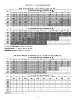
APPENDIX C — FAN PERFORMANCE


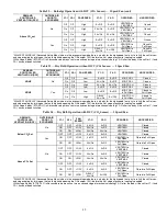
547K*04A SINGLE PHASE — 3 TON VERTICAL SUPPLY (RPM - BHP)

CFM

AVAILABLE EXTERNAL STATIC PRESSURE (in. wg)

0.2

0.4

0.6

0.8

1.0

RPM

BHP

RPM

BHP

RPM

BHP

RPM

BHP

RPM

BHP

900

1060

0.08

1325

0.16

1541

0.25

1718

0.35

1871

0.46

975

1103

0.09

1355

0.17

1572

0.27

1752

0.37

1906

0.48

1050

1150

0.11

1387

0.19

1602

0.29

1784

0.40

1941

0.51

1125

1198

0.12

1422

0.20

1632

0.30

1815

0.42

1974

0.54

1200

1249

0.14

1459

0.22

1662

0.32

1845

0.44

2005

0.56

1275

1303

0.15

1499

0.23

1694

0.34

1874

0.46

2036

0.59

1350

1357

0.17

1542

0.26

1728

0.36

1905

0.48

2066

0.61

1425

1413

0.20

1587

0.28

1765

0.38

1936

0.51

2095

0.64

1500

1469

0.22

1635

0.30

1803

0.41

1969

0.53

2126

0.67

CFM

AVAILABLE EXTERNAL STATIC PRESSURE (in. wg)

1.2

1.4

1.6

1.8

2.0

RPM

BHP

RPM

BHP

RPM

BHP

RPM

BHP

RPM

BHP

900

2006

0.56

2130

0.67

2244

0.79

2352

0.91

2454

1.03

975

2044

0.59

2168

0.71

2283

0.83

2391

0.95

1050

2080

0.63

2206

0.75

2322

0.87

2430

1.00

1125

2115

0.66

2242

0.78

2359

0.91

2468

1.05

1200

2148

0.69

2277

0.82

2396

0.96

1275

2180

0.72

2311

0.86

2431

1.00

1350

2211

0.75

2343

0.90

2465

1.04

1425

2241

0.78

2375

0.93

1500

2271

0.82

2405

0.97

Standard Static 1060-1890 RPM, 0.44 Max BHP

Medium Static 1060-2190 RPM, 0.71 Max BHP

High Static 1060-2490 RPM, 1.07 Max BHP

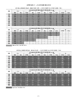
547K*04A SINGLE PHASE – STANDARD STATIC — 3 TON VERTICAL SUPPLY (RPM - VDC)

CFM

AVAILABLE EXTERNAL STATIC PRESSURE (in. wg)

0.2

0.4

0.6

0.8

1.0

RPM

Vdc

RPM

Vdc

RPM

Vdc

RPM

Vdc

RPM

Vdc

900

1060

5.6

1325

7.0

1541

8.2

1718

9.1

1871

9.9

975

1103

5.8

1355

7.2

1572

8.3

1752

9.3

1050

1150

6.1

1387

7.3

1602

8.5

1784

9.4

1125

1198

6.3

1422

7.5

1632

8.6

1815

9.6

1200

1249

6.6

1459

7.7

1662

8.8

1845

9.8

1275

1303

6.9

1499

7.9

1694

9.0

1874

9.9

1350

1357

7.2

1542

8.2

1728

9.1

1425

1413

7.5

1587

8.4

1765

9.3

1500

1469

7.8

1635

8.7

1803

9.5

CFM

AVAILABLE EXTERNAL STATIC PRESSURE (in. wg)

1.2

1.4

1.6

1.8

2.0

RPM

Vdc

RPM

Vdc

RPM

Vdc

RPM

Vdc

RPM

Vdc

900

975

1050

1125

1200

1275

1350

1425

1500

Standard Static 1060-1890 RPM

Содержание 547K

Страница 1: ...es 21 Completing Heater Installation 22 SMOKE DETECTORS 22 System 22 Controller 22 Smoke Detector Sensor 22 Smoke Detector Locations 23 Completing Installation of Return Air Smoke Detector 24 FIOP Smoke Detector Wiring and Response 24 SENSOR AND CONTROLLER TESTS 25 Sensor Alarm Test 25 Controller Alarm Test 25 Dirty Controller Test 25 Dirty Sensor Test 25 Changing the Dirt Sensor Test 26 Remote St...

Страница 2: ...ION HAZARD Failure to follow this warning could result in personal injury or death Before performing service or maintenance operations on unit LOCKOUT TAGOUT the main power switch to unit Electrical shock and rotating equipment could cause severe injury WARNING ELECTRICAL OPERATION HAZARD Failure to follow this warning could result in personal injury or death Units with convenience outlet circuits...

Страница 3: ...ll need to be periodically replaced or cleaned Filters RETURN AIR FILTERS Return air filters are disposable fiberglass media type Access to the filters is through the small lift out panel located on the rear side of the unit above the evaporator return air access panel See Fig 3 To remove the filters 1 Grasp the bottom flange of the upper panel 2 Lift up and swing the bottom out until the panel di...

Страница 4: ...the motor s maximum speed Fan speed should be set per job specification CFM cubic feet per minute and ESP external static pressure required and per Fan speed set up label includ ed on the unit s high voltage cover In some cases the Fan Speed Set Up label may already include the field setting if unit was previously installed Check the box on the lower half of the label to see if the field voltage s...

Страница 5: ...r in the Control Box 4 Connect a multimeter to the Vdc terminals on the UCB 5 Set the Range Switch to either A B or C per the Switch Range table 6 Using a straight blade screwdriver turn the Vdc control dial to fine tune the Vdc reading 7 Record the reading in the Field Setting field Low Speed Fan Adjustment 2 Pin DIP Switch The Low Speed 2 Pin DIP switch is located near the center of the UCB See ...

Страница 6: ... 6 8 7 1 7 4 7 7 8 0 8 4 8 7 0 1 0 6 6 9 7 1 7 4 7 7 7 9 8 2 8 5 8 8 0 1 0 8 7 5 7 7 8 0 8 2 8 5 8 7 9 0 0 1 1 0 8 1 8 3 8 5 8 7 9 0 0 1 1 2 8 6 8 8 9 0 9 2 0 1 1 4 9 1 9 3 9 5 0 1 1 6 1 8 2 0 9 6 0 1 Economizer 1 Stage E Heat 2 Stage E Heat UNIT MODEL NUMBER 4 1 7 5 6 9 8 7 7 7 10 0 0 2 0 3 0 2 0 3 0 2 0 3 0 2 0 3 0 2 0 3 0 2 0 3 0 2 0 3 0 2 0 3 9 8 9 9 9 7 9 9 9 5 9 7 10 0 9 2 9 5 9 8 9 3 9 6 9 ...

Страница 7: ...to press fit design of composite Rotor on Motor it is highly recommended that any time a motor is replaced the fan rotor is replaced as well The rest of the assembly may be reused See Fig 10 1 Unplug motor harness from control box harness and cut wire tie at the fan deck 2 Unplug connectors from stator temperature limit switch 3 Remove two screws at front of stator on fan deck 4 Slide fan assembly...

Страница 8: ... to motor Tighten to 23 in lb 2 6 Nm 7 Fit grommet on motor wire harness into keyhole feature on the side of the stator and pull wire harness out through grommet 8 Install rotor on motor by lining up one of 9 holes on com posite rotor with one of 9 holes on motor flange This can be done by adjusting motor and the top of the motor hub and aligning using a 3 16 in Allen key or similar pin Press fan ...

Страница 9: ...emoved with a vacuum cleaner If a vacuum cleaner is not available a soft non metal lic bristle brush may be used In either case the tool should be applied in the direction of the fins Coil surfaces can be easily damaged fin edges can be easily bent over and damage to the coating of a protected coil if the tool is applied across the fins NOTE Use of a water stream such as a garden hose against a su...

Страница 10: ...ls 10 Use a water hose or other suitable equipment to flush down between the 2 coil sections to remove dirt and debris If a coil cleaner is used be sure to rinse the coils completely before reassembly 11 Move the inner coil back into position Reinstall the lower and upper coil clips Reinstall the top panel and replace all screws Fig 16 Condenser Coil Clips Fig 17 Separating Coil Sections Totaline ...

Страница 11: ...unting screws 3 Slide filters out of unit 4 Clean coil using a commercial coil cleaner or dishwasher detergent in a pressurized spray canister Wash both sides of coil and flush with clean water For best results back flush toward return air section to remove foreign material Flush condensate pan after completion 5 Reinstall economizer and filters 6 Reconnect wiring 7 Replace access panels Refrigera...

Страница 12: ... the outlet of the evaporator coil The volume of refrigerant metered through the valve seat is dependent upon the following 1 Superheat temperature is sensed by cap tube sensing bulb on suction tube at outlet of evaporator coil This tempera ture is converted into pressure by refrigerant in the bulb pushing downward on the diaphragm which opens the valve using the push rods 2 The suction pressure a...

Страница 13: ...core screwed into the base See Fig 21 This check valve is permanently assembled into this core body and cannot be serviced separately replace the entire core body if neces sary Service tools are available from RCD that allow the re placement of the check valve core without having to recover the entire system refrigerant charge Apply compressor refrig erant oil to the check valve core s bottom o ri...

Страница 14: ... be 65 F 16 C USING COOLING CHARGING CHARTS Take the outdoor ambient temperature and read the liquid pres sure gage Refer to chart to determine what liquid temperature should be If liquid temperature is low add refrigerant If liquid temperature is high carefully recover some of the charge Re check the liquid pressure as charge is adjusted COOLING CHARGING CHARTS Fig 22 Cooling Charging Chart 3 Ton...

Страница 15: ...s caution may result in damage to com ponents The compressor is in a R 410A refrigerant system and uses a polyolester POE oil This oil is extremely hygroscopic meaning it absorbs water readily POE oils can absorb 15 times as much water as other oils designed for HCFC and CFC refrigerants Avoid exposure of the oil to the atmosphere WARNING FIRE EXPLOSION HAZARD Failure to follow this warning could ...

Страница 16: ...ls Filter Drier Replace whenever refrigerant system is exposed to atmo sphere Only use factory specified liquid line filter driers with working pressures no less than 650 psig 4482 kPa Condenser Fan Adjustment 1 Shut off unit power supply Install lockout tag 2 Remove condenser fan assembly grille motor and fan See Fig 26 3 Loosen fan hub setscrews 4 Adjust fan height by pushing fan until it stops ...

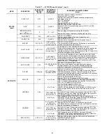
Страница 17: ...lace thermostat Faulty outdoor fan cooling or indoor fan heating motor or capacitor Replace faulty part Restriction in refrigerant system Locate restriction and remove Defective loader plug Determine cause and replace Compressor Operates Continuously Dirty air filter Replaced filter Unit undersized for load Decrease load or increase unit size Thermostat set too low cooling Reset thermostat Low ref...

Страница 18: ...r requirements and disconnect switch size and location Route 125 v power supply conductors into the bottom of the utility box containing the duplex receptacle Fig 29 Weatherproof Cover Installation Unit Powered Type A unit mounted transformer is factory installed to step down the main power supply voltage to the unit to 115 v at the du plex receptacle This option also includes a manual switch with...

Страница 19: ...ects be opened to de energize all pow er to the unit Treat all units as electrically energized until the convenience outlet power is also checked and de energization is confirmed Observe National Electrical Code Article 210 Branch Circuits for use of convenience outlets COMMERICAL DEFROST CONTROL On 547K units equipped with electro mechanical controls or the optional factory installed RTU Open con...

Страница 20: ...uence There are two time components The continuous run period and the test defrost cycle period The temperature component is provided by Defrost Thermostat 1 and 2 DFT1 and DFT2 mounted on the outdoor coil The continuous run period is a fixed time period between the end of the last defrost cycle or start of the current Heating cycle during which no defrost will be permitted This period can be set ...

Страница 21: ... the partition separating the indoor section with electric heat ers from the outdoor section The single point box has a hinged access cover See Fig 37 Fig 37 Typical Single Point Installation On 547K units all fuses are 60A Single point boxes contain ing fuses for 208 230 v applications use UL Class RK5 250 v fuses Bussmann FRNR 60 or Shawmut TR 60R Single point boxes for 460 v and 575 v applicati...

Страница 22: ...down the roof top unit in order to prevent smoke from circulating throughout the building It is not to be used as a life saving device Controller The controller see Fig 40 includes a controller housing a printed circuit board and a clear plastic cover The controller can be connected to one or two compatible duct smoke sensors The clear plastic cover is secured to the housing with a single captive ...

Страница 23: ...eck into a high pressure area The controller is locat ed on a bracket to the right of the return filter accessed through the lift off filter panel RETURN AIR SMOKE DETECTOR SENSOR WITHOUT ECONOMIZER The sampling tube is located across the return air opening on the unit basepan See Fig 43 The holes in the sampling tube face downward into the return air stream The sampling tube is con nected through...

Страница 24: ...l unit operations when a smoke condition is detected See Fig 47 Smoke Detector Wiring HIGHLIGHT A Smoke detector NC contact set will open on smoke alarm con dition de energizing the ORN conductor HIGHLIGHT B 24 v power signal using the ORN lead is removed at the smoke detector input on UCB all unit operations cease immediately RTU OPEN CONTROLS Unit operating functions fan cooling and heating are ...

Страница 25: ... no longer compensate for environmental changes is considered 100 dirty and requires cleaning or replacing A field provided SD MAG test magnet must be used to initiate a sensor dirty test The sensor s Dirty LED indicates the results of the dirty test as shown in Table 9 A C B D E IMPORTANT Failure to follow this ALERT can result in an unnecessary evacuation of the facility This test places the duc...

Страница 26: ...g continuously or sooner if conditions warrant 1 Disconnect power from the duct detector then remove the sensor s cover See Fig 49 2 Using a vacuum cleaner clean compressed air or a soft bristle brush remove loose dirt and debris from inside the sensor housing and cover Use isopropyl alcohol and a lint free cloth to remove dirt and other contaminants from the gasket on the sensor s cover FLASHES D...

Страница 27: ...moke detector The trouble condition must be cleared and then the duct smoke detec tor must be reset in order to restore it to the normal state RESETTING ALARM AND TROUBLE CONDITION TRIPS Manual reset is required to restore smoke detector systems to Normal operation For installations using two sensors the duct smoke detector does not differentiate which sensor signals an alarm or trouble condition ...

Страница 28: ...ischarge tube Trip setting is 630 psig 10 psig 4344 69 kPa when hot Reset is automatic at 505 psig 3482 kPa LOW PRESSURE SWITCH The system is protected against a loss of charge and low evapo rator coil loading condition by a low pressure switch located on the suction line near the compressor The switch is stem mounted Trip setting is 54 psig 5 psig 372 34 kPa Reset is automatic at 117 5 psig 807 3...

Страница 29: ...y provides the UL required clearance be tween high and low voltage wiring Pass the control wires through the hole provided in the corner post then feed the wires thorough the raceway to the RTU Open Connect the wires to the removable PCB connectors and then reconnect the connectors to the board Fig 51 RTU Open Control Module 1 LonWorks is a registered trademark of Echelon Corporation 2 Modbus is a...

Страница 30: ...ts only Economizers use direct drive damper actuators Fig 52 EconoMi er X Component Locations Fig 53 EconoMi er IV Component Locations Fig 54 EconoMi er2 Component Locations IMPORTANT Any economizer that meets the economizer requirements as laid out in California s Title 24 mandatory section 120 2 fault detection and diagnostics and or pre scriptive section 140 4 life cycle tests damper leakage 5 ...

Страница 31: ...er2 is operated by a 4 to 20 mA signal from an existing field supplied control ler See Fig 55 for wiring information 4 3 5 2 8 6 7 1 10 11 9 12 PINK VIOLET BLACK BLUE YELLOW RUN RED WHITE ECONOMI ER2 PLUG DIRECT DRIVE ACTUATOR 4 20mA SIGNAL OAT SENSOR ACTUATOR CONTROL 4 20mA ACTUATOR FEEDBACK 2 10VDC TRANSFORMER GROUND ORANGE 500 OHM RESISTOR ...

Страница 32: ...ram is available to help with EconoMi er IV training and troubleshooting See Fig 57 and Table 11 for further details Fig 56 EconoMi er IV Functional View LEGEND Fig 57 Typical EconoMi er IV W7212 Controller Wiring IMPORTANT For 547K rooftop units EconoMi er IV is available as a factory installed option for 04 06 units only DCV Demand Controlled Ventilation IAQ Indoor Air Quality LA Low Ambient Loc...

Страница 33: ...rmis tor located on the fan deck See Fig 59 This sensor is factory in stalled The operating range of temperature measurement is 0 F to 158 F 18 C to 70 C See Table 12 on page 34 for sensor tem perature resistance values Fig 59 Supply Air Sensor Location The temperature sensor looks like an eyelet terminal with wires running to it The sensor is located in the crimp end and is sealed from moisture O...

Страница 34: ...mper moves to its minimum position The outdoor enthalpy changeover set point is set with the out door enthalpy set point potentiometer on the EconoMi er IV controller The set points are A B C and D See Fig 63 and 64 The factory installed 620 ohm jumper must be in place across terminals SR and SR on the EconoMi er IV controller Fig 60 Outdoor Air Temperature Changeover Set Points Differential Entha...

Страница 35: ...URN DUCT STATIC PRESSURE in wg RELIEF FLOW CFM 3 5 Ton Vertical Economizers Vertical Economizers 0 1000 2000 3000 4000 5000 6000 RETURN AIR FLOW CFM 3 5 Ton HORIZONTAL ECONOMIZER BAROMETRIC RELIEF FLOW HORIZONTAL ECONOMIZER RETURN AIR PRESSURE DROP VERTICAL ECONOMIZER BAROMETRIC RELIEF FLOW VERTICAL ECONOMIZER RETURN AIR PRESSURE DROP 0 0 1 0 2 0 3 0 4 RETURN DUCT STATIC PRESSURE DROP in wg 6 Ton ...

Страница 36: ... ventilation position should be turned fully clockwise Adjust the minimum position potentiometer to allow the mini mum amount of outdoor air as required by local codes to enter the building Make minimum position adjustments with at least 10 F temperature difference between the outdoor and return air temperatures To determine the minimum position setting perform the fol lowing procedure 1 Calculate...

Страница 37: ...ntilation rate of 20 or base plus 15 cfm per person Use Fig 65 to determine the maximum setting of the CO2 sensor For example an 1100 ppm set point relates to a 15 cfm per person design Use the 1100 ppm curve on Fig 65 to find the point when the CO2 sensor output will be 6 7 volts Line up the point on the graph with the left side of the chart to determine that the range configuration for the CO2 s...

Страница 38: ...MUM AND MAXIMUM POSITION To check the DCV minimum and maximum position 1 Make sure EconoMi er IV preparation procedure has been performed 2 Connect a 9 v battery to AQ positive node and AQ1 negative node The DCV LED should turn on The actua tor should drive to between 90 and 95 open 3 Turn the DCV Maximum Position potentiometer to mid point The actuator should drive to between 20 and 80 open 4 Tur...

Страница 39: ...the system The W7220 economizer module pro vides the basic inputs and outputs to provide simple economizer control When used with the optional sensors the economizer module provides more advanced economizer functionality S Bus Enthalpy Control Sensors The sensor is a combination temperature and humidity sensor which is powered by and communicates on the S Bus Up to three sensors may be configured ...

Страница 40: ...Temperature 40 to 150 F 40 to 65 C Exception of display operation down to 4 F 20 C with full recovery at 4 F 20 C from exposure to 40 F 40 C Storage Temperature 40 to 150 F 40 to 65 C Shipping Temperature 40 to 150 F 40 to 65 C Relative Humidity 5 to 95 RH non condensing ECONOMIZER MODULE WIRING DETAILS Use Fig 68 and Tables 13 and 14 to locate the wiring terminals for the Economizer module NOTE T...

Страница 41: ...nges Menu structure and selection User Interface The user interface consists of a 2 line LCD display and a 4 but ton keypad on the front of the economizer controller Keypad Use the four navigation buttons see Fig 71 to scroll through the menus and menu items select menu items and to change parameter and configuration settings To use the keypad when working with menus Press the Up arrow button to m...

Страница 42: ...u Up Exit button to return to the previous menu Menu Structure Table 17 illustrates the complete hierarchy of menus and pa rameters for the EconoMi er X system The Menus in display order are STATUS SETPOINTS SYSTEM SETUP ADVANCED SETUP CHECKOUT ALARMS NOTE Some parameters in the menus use the letters MA or MAT indicating a mixed air temperature sensor location before the cooling coil This unit app...

Страница 43: ... and displays measured discharge temperature Displays _ _ _F if sensor sends invalid value if not connected short or out of range OA TEMP _ _ _ F or _ _ _ C 40 F to 140 F 40 C to 60 C OUTSIDE AIR TEMP Displays measured value of outdoor air temperature Displays _ _ _F if sensor sends invalid value short or out of range OA HUM _ _ 0 to 100 OUTSIDE AIR RELATIVE HUMIDITY Displays measured value of out...

Страница 44: ... curves DCV SET 1100ppm 500 to 2000 ppm increment by 100 DEMAND CONTROLLED VENTILATION Displays only if CO2 sensor is connected Set point for Demand Controlled Ventilation of space Above the set point the OA dampers will modulate open to bring in additional OA to maintain a space ppm level below the set point MIN POS 2 8 V 2 to 10 vdc VENTILATION MINIMUM POSITION Displays ONLY if a CO2 sensor is N...

Страница 45: ... vac out for second exhaust fan SYS use output as an alarm signal OCC INPUT INPUT or ALWAYS OCCUPIED MODE BY EXTERNAL SIGNAL When using a setback thermostat with occupancy out 24 vac the 24 vac is input INPUT to the OCC terminal If no occupancy output from the thermostat then change program to ALWAYS OR add a jumper from terminal R to OCC terminal FACTORY DEFAULT NO NO or YES Resets all set points...

Страница 46: ...he fully closed position CONNECT Y1 O N A N A Closes the Y1 O relay Y1 O CONNECT Y2 O N A N A Closes the Y2 O relay Y2 O CONNECT AUX1 O N A N A Energizes the AUX output If Aux setting is NONE no action taken ERV 24 vac out Turns on or signals an ERV that the conditions are not good for economizing but are for ERV operation SYS 24 vac out Issues a system alarm CONNECT EXH1 N A N A Closes the power ...

Страница 47: ...ration with a 2 speed indoor fan with or without DCV see Tables 23 and 24 For enthalpy operation with a 2 speed indoor fan with or without DCV see Tables 25 and 26 ALARMS cont FREEZE ALARM N A N A Check if outdoor temperature is below the LOW Temp Lockout on set point menu Check if Mixed air temperature on STATUS menu is below the Lo Set point on Advanced menu When conditions are back in normal ra...

Страница 48: ...High 0 v Off 0 v Off VENTMIN Closed On Off High 0 v Off 0 v Off VENTMIN to Full Open Closed to Full Open On On High 24 v On 0 v Off VENTMIN to Full Open Closed to Full Open Above CO2 set No Off Off High 0 v Off 0 v Off VENTMIN to VENTMAX Closed On Off High 24 v On 0 v Off VENTMIN to VENTMAX Closed On On High 24 v On 24 v On VENTMIN to VENTMAX Closed Yes Off Off High 0 v Off 0 v Off VENTMIN to VENT...

Страница 49: ...gh 0 v Off 0 v Off VENTMIN L to VENTMAX Closed On Off High 0 v Off 0 v Off VENTMIN to Full Open Closed to Full Open On On High DELAY 24 v On 0 v Off VENTMIN to Full Open Closed to Full Open Table 22 Enthalpy Operation with DCV CO2 Sensor 1 Speed Fan cont DEMAND CONTROLLED VENTILATION DCV OUTSIDE AIR GOOD TO ECONOMIZE Y1 I Y2 I FAN SPEED Y1 O Y2 O OCCUPIED UNOCCUPIED Table 23 Dry Bulb Operation wit...

Страница 50: ... 25 Enthalpy Operation without DCV CO2 Sensor 2 Speed Fan DEMAND CONTROLLED VENTILATION DCV OUTSIDE AIR GOOD TO ECONOMIZE Y1 I Y2 I FAN SPEED Y1 O Y2 O OCCUPIED UNOCCUPIED NO CO2 SENSOR NO OFF OFF LOW 0v Off 0v Off MIN POS Closed ON OFF LOW 24v On 0v Off MIN POS Closed ON ON HIGH 24v On 24v On MIN POS Closed YES OFF OFF LOW 0v Off 0v Off MIN POS Closed ON OFF LOW 0v Off 0v Off MIN POS to Full Open...

Страница 51: ...e of the keypad see Interface Overview on page 41 Power Up After the W7220 module is mounted and wired apply power Initial Menu Display On initial start up Honeywell displays on the first line and econo mizer W7220 on the second line After a brief pause the revision of the software appears on the first line and the second line will be blank Power Loss Outage or Brownout All set points and advanced...

Страница 52: ...t up units with optional direct digital controls DDC The DDC s Service Test function should be used to assist in the base unit start up and also allows verification of output operation Con troller configuration is also part of start up This is especially important when field accessories have been added to the unit The factory pre configures options installed at the factory There may also be additi...

Страница 53: ...room temperature Com pressor will shut off Evaporator fan will shut off after a 30 second delay To shut off unit set system selector switch at OFF position Resetting thermostat at a position above room temperature shuts unit off temporarily until space temperature exceeds ther mostat setting Heating To start unit turn on main power supply Set system selector switch to the HEAT position and set the...

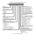
Страница 54: ... Al Cu B Precoat Al Cu Al Cu C E coat Al Cu Al Cu D E coat Al Cu E coat Al Cu E Cu Cu Al Cu F Cu Cu Cu Cu M Al Cu Al Cu Louvered Hail Guard N Precoat Al Cu Al Cu Louvered Hail Guard P E coat Al Cu Al Cu Louvered Hail Guard Q E coat Al Cu E coat Al Cu Louvered Hail Guard R Cu Cu Al Cu Louvered Hail Guard S Cu Cu Cu Cu Louvered Hail Guard Voltage E 460 3 60 J 208 230 1 60 P 208 230 3 60 T 575 3 60 O...

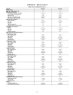
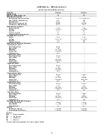
Страница 55: ... Static 1 Phase Motor Qty Drive Type 1 Direct 1 Direct Max Cont BHP 0 71 1 06 RPM Range 219 2190 217 2170 Fan Qty Type 1 Vane Axial 1 Vane Axial Fan Diameter in 16 6 16 6 High Static 1 Phase Motor Qty Drive Type 1 Direct 1 Direct Max Cont BHP 1 07 1 53 RPM Range 249 2490 246 2460 Fan Qty Type 1 Vane Axial 1 Vane Axial Fan Diameter in 16 6 16 6 Standard Static 3 Phase Motor Qty Drive Type 1 Direct ...

Страница 56: ... Diameter in 16 6 Medium Static 1 Phase Motor Qty Drive Type 1 Direct Max Cont BHP 1 44 RPM Range 239 2390 Fan Qty Type 1 Vane Axial Fan Diameter in 16 6 High Static 1 Phase Motor Qty Drive Type 1 Direct Max Cont BHP 1 96 RPM Range 266 2660 Fan Qty Type 1 Vane Axial Fan Diameter in 16 6 Standard Static 3 Phase Motor Qty Drive Type 1 Direct 1 Direct Max Cont BHP 1 06 1 31 RPM Range 215 2150 230 230...

Страница 57: ...ance tables offer motor drive recommendations In cases when two motor drive combinations would work the lower horsepower option is recommended 6 The EPACT Energy Policy Act of 1992 regulates energy requirements for specific types of indoor fan motors Motors regu lated by EPACT include any general purpose T frame three digit 143 and larger single speed foot mounted polyphase squirrel cage induction...

Страница 58: ...391 0 95 1050 2080 0 63 2206 0 75 2322 0 87 2430 1 00 1125 2115 0 66 2242 0 78 2359 0 91 2468 1 05 1200 2148 0 69 2277 0 82 2396 0 96 1275 2180 0 72 2311 0 86 2431 1 00 1350 2211 0 75 2343 0 90 2465 1 04 1425 2241 0 78 2375 0 93 1500 2271 0 82 2405 0 97 Standard Static 1060 1890 RPM 0 44 Max BHP Medium Static 1060 2190 RPM 0 71 Max BHP High Static 1060 2490 RPM 1 07 Max BHP 547K 04A SINGLE PHASE S...

Страница 59: ...tatic 1060 2190 RPM 547K 04A SINGLE PHASE HIGH STATIC 3 TON VERTICAL SUPPLY RPM VDC CFM AVAILABLE EXTERNAL STATIC PRESSURE in wg 0 2 0 4 0 6 0 8 1 0 RPM Vdc RPM Vdc RPM Vdc RPM Vdc RPM Vdc 900 1060 4 3 1325 5 3 1541 6 2 1718 6 9 1871 7 5 975 1103 4 4 1355 5 4 1572 6 3 1752 7 0 1906 7 7 1050 1150 4 6 1387 5 6 1602 6 4 1784 7 2 1941 7 8 1125 1198 4 8 1422 5 7 1632 6 6 1815 7 3 1974 7 9 1200 1249 5 0...

Страница 60: ...391 0 95 1050 2080 0 63 2206 0 75 2322 0 87 2430 1 00 1125 2115 0 66 2242 0 78 2360 0 92 2469 1 05 1200 2148 0 69 2277 0 82 2396 0 96 1275 2180 0 72 2311 0 86 2431 1 00 1350 2211 0 75 2343 0 90 2465 1 04 1425 2241 0 78 2375 0 93 1500 2271 0 82 2405 0 97 Standard Static 1060 1890 RPM 0 44 Max BHP Medium Static 1060 2190 RPM 0 71 Max BHP High Static 1060 2490 RPM 1 07 Max BHP 547K 04A THREE PHASE ST...

Страница 61: ...tatic 1060 2190 RPM 547K 04A THREE PHASE HIGH STATIC 3 TON VERTICAL SUPPLY RPM VDC CFM AVAILABLE EXTERNAL STATIC PRESSURE in wg 0 2 0 4 0 6 0 8 1 0 RPM Vdc RPM Vdc RPM Vdc RPM Vdc RPM Vdc 900 1060 4 3 1325 5 3 1541 6 2 1718 6 9 1871 7 5 975 1103 4 4 1355 5 4 1572 6 3 1752 7 0 1906 7 7 1050 1150 4 6 1387 5 6 1602 6 4 1784 7 2 1941 7 8 1125 1198 4 8 1422 5 7 1632 6 6 1815 7 3 1974 7 9 1200 1249 5 0 ...

Страница 62: ...1 20 2344 1 39 2450 1 58 1500 2026 0 89 2148 1 06 2264 1 25 2373 1 44 1600 2062 0 94 2181 1 11 2296 1 30 2404 1 49 1700 2099 0 99 2217 1 16 2328 1 35 2435 1 54 1800 2138 1 04 2254 1 22 2363 1 41 1900 2179 1 10 2292 1 28 2400 1 47 2000 2221 1 16 2332 1 34 2438 1 54 Standard Static 1095 1900 RPM 0 72 Max BHP Medium Static 1095 2170 RPM 1 06 Max BHP High Static 1095 2460 RPM 1 53 Max BHP 547K 05A SIN...

Страница 63: ... RPM 547K 05A SINGLE PHASE HIGH STATIC 4 TON VERTICAL SUPPLY RPM VDC CFM AVAILABLE EXTERNAL STATIC PRESSURE in wg 0 2 0 4 0 6 0 8 1 0 RPM Vdc RPM Vdc RPM Vdc RPM Vdc RPM Vdc 1200 1094 4 4 1302 5 3 1484 6 0 1646 6 7 1794 7 3 1300 1150 4 7 1347 5 5 1523 6 2 1681 6 8 1826 7 4 1400 1209 4 9 1395 5 7 1565 6 4 1719 7 0 1860 7 6 1500 1269 5 2 1444 5 9 1608 6 5 1758 7 1 1897 7 7 1600 1332 5 4 1496 6 1 165...

Страница 64: ...1 06 2263 1 24 2373 1 44 2478 1 63 1600 2062 0 94 2181 1 11 2295 1 29 2403 1 49 2507 1 69 1700 2099 0 99 2217 1 16 2328 1 35 2435 1 54 2538 1 75 1800 2138 1 04 2254 1 22 2363 1 40 2469 1 60 2570 1 81 1900 2180 1 10 2292 1 28 2400 1 47 2503 1 67 2603 1 87 2000 2222 1 16 2332 1 34 2438 1 54 2540 1 74 2638 1 95 Standard Static 1094 1900 RPM 0 72 Max BHP Medium Static 1094 2170 RPM 1 06 Max BHP High S...

Страница 65: ...TON VERTICAL SUPPLY RPM VDC CFM AVAILABLE EXTERNAL STATIC PRESSURE in wg 0 2 0 4 0 6 0 8 1 0 RPM Vdc RPM Vdc RPM Vdc RPM Vdc RPM Vdc 1200 1094 4 1 1302 4 9 1484 5 6 1646 6 2 1794 6 7 1300 1150 4 3 1347 5 1 1524 5 7 1681 6 3 1826 6 9 1400 1209 4 5 1395 5 2 1565 5 9 1719 6 5 1860 7 0 1500 1269 4 8 1444 5 4 1608 6 0 1759 6 6 1897 7 1 1600 1332 5 0 1496 5 6 1654 6 2 1800 6 8 1935 7 3 1700 1396 5 2 154...

Страница 66: ...2148 1 04 2256 1 21 2359 1 38 2458 1 56 2553 1 75 2125 2200 1 11 2305 1 28 2407 1 46 2504 1 64 2597 1 83 2250 2254 1 20 2357 1 37 2456 1 55 2551 1 73 2643 1 93 2375 2310 1 28 2410 1 46 2507 1 64 2600 1 83 2500 2368 1 38 2465 1 56 2560 1 75 2651 1 94 Standard Static 1228 2150 RPM 1 06 Max BHP Medium Static 1228 2390 RPM 1 44 Max BHP High Static 1228 2660 RPM 1 96 Max BHP 547K 06A SINGLE PHASE STAND...

Страница 67: ...9 9 Medium Static 1228 2390 RPM 547K 06A SINGLE PHASE HIGH STATIC 5 TON VERTICAL SUPPLY RPM VDC CFM AVAILABLE EXTERNAL STATIC PRESSURE in wg 0 2 0 4 0 6 0 8 1 0 RPM Vdc RPM Vdc RPM Vdc RPM Vdc RPM Vdc 1500 1228 4 6 1394 5 2 1554 5 8 1701 6 4 1836 6 9 1625 1305 4 9 1457 5 5 1609 6 0 1750 6 6 1882 7 1 1750 1384 5 2 1523 5 7 1666 6 3 1802 6 8 1930 7 3 1875 1466 5 5 1592 6 0 1726 6 5 1857 7 0 1981 7 4...

Страница 68: ...2256 1 21 2359 1 38 2458 1 56 2553 1 75 2125 2200 1 11 2305 1 28 2407 1 46 2504 1 64 2597 1 83 2250 2254 1 20 2357 1 37 2456 1 55 2551 1 73 2643 1 93 2375 2310 1 28 2410 1 46 2507 1 64 2600 1 83 2690 2 03 2500 2368 1 38 2465 1 56 2560 1 75 2651 1 94 2739 2 14 Standard Static 1228 2150 RPM 1 06 Max BHP Medium Static 1228 2390 RPM 1 44 Max BHP High Static 1228 2836 RPM 2 43 Max BHP 547K 06A THREE PH...

Страница 69: ...um Static 1228 2390 RPM 547K 06A THREE PHASE HIGH STATIC 5 TON VERTICAL SUPPLY RPM VDC CFM AVAILABLE EXTERNAL STATIC PRESSURE in wg 0 2 0 4 0 6 0 8 1 0 RPM Vdc RPM Vdc RPM Vdc RPM Vdc RPM Vdc 1500 1228 4 3 1394 4 9 1554 5 5 1701 6 0 1836 6 5 1625 1305 4 6 1457 5 1 1609 5 7 1750 6 2 1882 6 6 1750 1384 4 9 1523 5 4 1666 5 9 1802 6 4 1930 6 8 1875 1466 5 2 1592 5 6 1726 6 1 1857 6 5 1981 7 0 2000 154...

Страница 70: ... 73 2643 1 93 2400 2321 1 30 2421 1 48 2517 1 66 2610 1 85 2700 2 05 2550 2392 1 42 2488 1 60 2581 1 79 2672 1 98 2759 2 18 2700 2465 1 55 2557 1 73 2648 1 93 2736 2 13 2821 2 33 2850 2541 1 70 2630 1 88 2717 2 08 2802 2 28 3000 2621 1 86 2705 2 05 2788 2 24 Standard Static 1416 2300 RPM 1 31 Max BHP Medium Static 1416 2530 RPM 1 76 Max BHP High Static 1416 2836 RPM 2 43 Max BHP 547K 07N THREE PHA...

Страница 71: ...um Static 1416 2530 RPM 547K 07N THREE PHASE HIGH STATIC 6 TON VERTICAL SUPPLY RPM VDC CFM AVAILABLE EXTERNAL STATIC PRESSURE in wg 0 2 0 4 0 6 0 8 1 0 RPM Vdc RPM Vdc RPM Vdc RPM Vdc RPM Vdc 1800 1416 5 0 1549 5 5 1690 6 0 1824 6 4 1950 6 9 1950 1516 5 3 1635 5 8 1764 6 2 1891 6 7 2012 7 1 2100 1616 5 7 1724 6 1 1841 6 5 1961 6 9 2078 7 3 2250 1718 6 1 1815 6 4 1924 6 8 2036 7 2 2146 7 6 2400 182...

Страница 72: ...2189 0 73 2309 0 86 2421 0 99 1125 2088 0 63 2219 0 76 2341 0 89 2454 1 03 1200 2117 0 66 2249 0 79 2372 0 93 2486 1 07 1275 2146 0 69 2278 0 82 2402 0 97 1350 2174 0 72 2307 0 86 2431 1 00 1425 2202 0 74 2336 0 89 2460 1 04 1500 2230 0 77 2364 0 92 2488 1 07 Standard Static 1036 1890 RPM 0 44 Max BHP Medium Static 1036 2190 RPM 0 71 Max BHP High Static 1036 2490 RPM 1 07 Max BHP 547K 04A SINGLE P...

Страница 73: ...1036 2190 RPM 547K 04A SINGLE PHASE HIGH STATIC 3 TON HORIZONTAL SUPPLY RPM VDC CFM AVAILABLE EXTERNAL STATIC PRESSURE in wg 0 2 0 4 0 6 0 8 1 0 RPM Vdc RPM Vdc RPM Vdc RPM Vdc RPM Vdc 900 1036 4 2 1301 5 2 1517 6 1 1698 6 8 1855 7 4 975 1077 4 3 1331 5 3 1546 6 2 1727 6 9 1885 7 6 1050 1119 4 5 1362 5 5 1574 6 3 1755 7 0 1915 7 7 1125 1164 4 7 1394 5 6 1603 6 4 1783 7 2 1944 7 8 1200 1211 4 9 142...

Страница 74: ...189 0 73 2309 0 86 2421 0 99 1125 2088 0 63 2219 0 76 2341 0 89 2454 1 03 1200 2117 0 66 2249 0 79 2372 0 93 2485 1 07 1275 2146 0 69 2278 0 82 2401 0 96 1350 2174 0 72 2307 0 86 2431 1 00 1425 2202 0 74 2335 0 89 2460 1 04 1500 2231 0 77 2364 0 92 2488 1 07 Standard Static 1136 1890 RPM 0 44 Max BHP Medium Static 1136 2190 RPM 0 71 Max BHP High Static 1136 2490 RPM 1 07 Max BHP 547K 04A THREE PHA...

Страница 75: ...1136 2190 RPM 547K 04A THREE PHASE HIGH STATIC 3 TON HORIZONTAL SUPPLY RPM VDC CFM AVAILABLE EXTERNAL STATIC PRESSURE in wg 0 2 0 4 0 6 0 8 1 0 RPM Vdc RPM Vdc RPM Vdc RPM Vdc RPM Vdc 900 1036 4 2 1301 5 2 1517 6 1 1698 6 8 1855 7 4 975 1076 4 3 1330 5 3 1545 6 2 1727 6 9 1885 7 6 1050 1119 4 5 1361 5 5 1573 6 3 1756 7 1 1915 7 7 1125 1164 4 7 1395 5 6 1602 6 4 1784 7 2 1944 7 8 1200 1211 4 9 1429...

Страница 76: ... 1 17 2356 1 36 1500 2023 0 86 2149 1 03 2269 1 21 2382 1 40 1600 2053 0 89 2178 1 07 2297 1 25 2409 1 45 1700 2084 0 93 2209 1 11 2326 1 30 2437 1 49 1800 2117 0 98 2239 1 15 2356 1 34 1900 2151 1 02 2272 1 20 2386 1 39 2000 2187 1 07 2305 1 25 2418 1 45 Standard Static 1066 1900 RPM 0 72 Max BHP Medium Static 1066 2170 RPM 1 06 Max BHP High Static 1066 2460 RPM 1 53 Max BHP 547K 05A SINGLE PHASE...

Страница 77: ... 1066 2170 RPM 547K 05A SINGLE PHASE HIGH STATIC 4 TON HORIZONTAL SUPPLY RPM VDC CFM AVAILABLE EXTERNAL STATIC PRESSURE in wg 0 2 0 4 0 6 0 8 1 0 RPM Vdc RPM Vdc RPM Vdc RPM Vdc RPM Vdc 1200 1066 4 3 1280 5 2 1473 6 0 1644 6 7 1798 7 3 1300 1120 4 6 1320 5 4 1506 6 1 1674 6 8 1826 7 4 1400 1177 4 8 1363 5 5 1541 6 3 1705 6 9 1856 7 5 1500 1236 5 0 1409 5 7 1579 6 4 1739 7 1 1886 7 7 1600 1297 5 3 ...

Страница 78: ... 2269 1 21 2382 1 40 2490 1 60 1600 2053 0 89 2178 1 07 2297 1 25 2409 1 45 2516 1 65 1700 2085 0 93 2208 1 11 2326 1 30 2437 1 49 2543 1 69 1800 2117 0 98 2240 1 16 2356 1 34 2466 1 54 2571 1 75 1900 2152 1 02 2272 1 20 2386 1 39 2496 1 59 2600 1 80 2000 2188 1 07 2306 1 25 2418 1 45 2526 1 65 2630 1 86 Standard Static 1067 1900 RPM 0 72 Max BHP Medium Static 1067 2170 RPM 1 06 Max BHP High Stati...

Страница 79: ...IC 4 TON HORIZONTAL SUPPLY RPM VDC CFM AVAILABLE EXTERNAL STATIC PRESSURE in wg 0 2 0 4 0 6 0 8 1 0 RPM Vdc RPM Vdc RPM Vdc RPM Vdc RPM Vdc 1200 1067 4 0 1280 4 8 1473 5 5 1645 6 2 1798 6 8 1300 1121 4 2 1320 5 0 1506 5 7 1675 6 3 1827 6 9 1400 1177 4 4 1363 5 1 1542 5 8 1706 6 4 1856 7 0 1500 1237 4 7 1409 5 3 1579 5 9 1739 6 5 1887 7 1 1600 1297 4 9 1458 5 5 1620 6 1 1774 6 7 1919 7 2 1700 1359 ...

Страница 80: ...6 1 12 2336 1 29 2441 1 48 2541 1 66 2125 2157 1 02 2268 1 18 2375 1 36 2478 1 54 2578 1 73 2250 2206 1 08 2313 1 25 2417 1 43 2518 1 61 2616 1 81 2375 2258 1 16 2361 1 33 2461 1 50 2560 1 69 2655 1 89 2500 2312 1 24 2411 1 41 2508 1 59 2604 1 78 Standard Static 1197 2150 RPM 1 06 Max BHP Medium Static 1197 2390 RPM 1 44 Max BHP High Static 1197 2660 RPM 1 96 Max BHP 547K 06A SINGLE PHASE STANDARD...

Страница 81: ...2312 9 7 Medium Static 1197 2390 RPM 547K 06A SINGLE PHASE HIGH STATIC 5 TON HORIZONTAL SUPPLY RPM VDC CFM AVAILABLE EXTERNAL STATIC PRESSURE in wg 0 2 0 4 0 6 0 8 1 0 RPM Vdc RPM Vdc RPM Vdc RPM Vdc RPM Vdc 1500 1197 4 5 1360 5 1 1525 5 7 1679 6 3 1822 6 8 1625 1271 4 8 1421 5 3 1574 5 9 1721 6 5 1860 7 0 1750 1348 5 1 1485 5 6 1627 6 1 1767 6 6 1901 7 1 1875 1425 5 4 1553 5 8 1684 6 3 1817 6 8 1...

Страница 82: ...2 2336 1 29 2441 1 48 2541 1 66 2125 2157 1 02 2268 1 18 2376 1 36 2479 1 54 2578 1 73 2250 2206 1 08 2313 1 25 2418 1 43 2518 1 61 2616 1 81 2375 2258 1 16 2361 1 33 2462 1 50 2560 1 69 2656 1 89 2500 2312 1 24 2411 1 41 2508 1 59 2604 1 78 2698 1 97 Standard Static 1196 2150 RPM 1 06 Max BHP Medium Static 1196 2390 RPM 1 44 Max BHP High Static 1196 2836 RPM 2 43 Max BHP 547K 06A THREE PHASE STAN...

Страница 83: ... 9 7 Medium Static 1196 2390 RPM 547K 06A THREE PHASE HIGH STATIC 5 TON HORIZONTAL SUPPLY RPM VDC CFM AVAILABLE EXTERNAL STATIC PRESSURE in wg 0 2 0 4 0 6 0 8 1 0 RPM Vdc RPM Vdc RPM Vdc RPM Vdc RPM Vdc 1500 1196 4 2 1360 4 8 1525 5 4 1679 5 9 1822 6 4 1625 1271 4 5 1421 5 0 1574 5 6 1721 6 1 1860 6 6 1750 1348 4 8 1485 5 2 1627 5 7 1767 6 2 1901 6 7 1875 1425 5 0 1553 5 5 1684 5 9 1817 6 4 1945 6...

Страница 84: ... 2268 1 18 2370 1 34 2471 1 52 2568 1 71 2664 1 90 2550 2335 1 28 2432 1 45 2528 1 62 2622 1 81 2714 2 01 2700 2405 1 40 2497 1 56 2589 1 74 2679 1 93 2768 2 13 2850 2479 1 53 2566 1 69 2653 1 87 2740 2 06 2826 2 26 3000 2556 1 67 2639 1 84 2722 2 02 2804 2 21 Standard Static 1378 2300 RPM 1 31 Max BHP Medium Static 1378 2530 RPM 1 76 Max BHP High Static 1378 2836 RPM 2 43 Max BHP 547K 07N THREE P...

Страница 85: ... 2479 9 8 3000 Medium Static 1378 2530 RPM 547K 07N THREE PHASE HIGH STATIC 6 TON HORIZONTAL SUPPLY RPM VDC CFM AVAILABLE EXTERNAL STATIC PRESSURE in wg 0 2 0 4 0 6 0 8 1 0 RPM Vdc RPM Vdc RPM Vdc RPM Vdc RPM Vdc 1800 1378 4 9 1512 5 3 1649 5 8 1786 6 3 1918 6 8 1950 1473 5 2 1594 5 6 1721 6 1 1848 6 5 1973 7 0 2100 1569 5 5 1680 5 9 1796 6 3 1915 6 8 2032 7 2 2250 1666 5 9 1769 6 2 1876 6 6 1986 ...

Страница 86: ...48TC003166 48TC003217 88 48TC003163 94 208 230 3 60 48TC003162 95 460 575 3 60 48TC003164 96 07 Electro Mechanical W7220 Controller 208 230 3 60 48TC003160 89 48TC003162 95 460 575 3 60 48TC003161 90 48TC003164 96 04 06 RTU Open Controller Factory Option 208 230 1 60 48TC003166 48TC003214 91 48TC003163 94 208 230 3 60 48TC003162 95 460 575 3 60 48TC003164 96 07 RTU Open Controller Factory Option 2...

Страница 87: ...87 APPENDIX D WIRING DIAGRAMS Fig B 547K 04 06 Electro Mechanical Control Wiring Diagram 208 230 3 60 with W7212 Control ...

Страница 88: ...88 APPENDIX D WIRING DIAGRAMS Fig C 547K 04 06 Electro Mechanical Control Wiring Diagram All Voltages with W7220 Control ...

Страница 89: ...89 APPENDIX D WIRING DIAGRAMS Fig D 547K 07 Electro Mechanical Control Wiring Diagram 208 230 3 60 with W7220 Control ...

Страница 90: ...90 APPENDIX D WIRING DIAGRAMS Fig E 547K 07 Electro Mechanical Control Wiring Diagram 460 575 3 60 with W7220 Control ...

Страница 91: ...91 APPENDIX D WIRING DIAGRAMS Fig F 547K 04 06 Units All Voltages with Optional Factory Installed RTU Open Controller ...

Страница 92: ...92 APPENDIX D WIRING DIAGRAMS Fig G 547K 07 208 230 3 60 Units with Optional Factory Installed RTU Open Controller ...

Страница 93: ...93 APPENDIX D WIRING DIAGRAMS Fig H 547K 07 460 575 3 60 Units with Optional Factory Installed RTU Open Controller ...

Страница 94: ...94 APPENDIX D WIRING DIAGRAMS Fig I 547K 04 06 Power Wiring Diagram 208 230 1 60 ...

Страница 95: ...95 APPENDIX D WIRING DIAGRAMS Fig J 547K 04 07 Power Wiring Diagram 208 230 3 60 ...

Страница 96: ...96 APPENDIX D WIRING DIAGRAMS Fig K 5047K 04 07 Power Wiring Diagram 460 575 3 60 ...

Страница 97: ...97 APPENDIX E LOW AMBIENT CONTROL SENSOR LOCATION Fig L 547K 04 Outdoor Circuiting Fig M 547K 05 Outdoor Circuiting SENSOR LOCATION SENSOR LOCATION ...

Страница 98: ...hout notice and without obligations Replaces New 2020 Carrier Cat No 04 53547004 01 Edition Date 12 2020 Printed in U S A Form No 547K 4 7 01 APPENDIX E LOW AMBIENT CONTROL SENSOR LOCATION Fig N 547K 06 Outdoor Circuiting Fig O 547K 07 Outdoor Circuiting SENSOR LOCATION SENSOR LOCATION ...

Страница 99: ...vel Y N _____ Verify that fan assembly is free of obstructions and rotor spins freely Y N _____ Verify that scroll compressors are rotating in the correct direction Y N _____ Verify installation of thermostat Y N _____ III START UP ELECTRICAL Supply Voltage L1 L2_____________ L2 L3_____________ L3 L1_____________ Compressor Amps 1 L1 _____________ L2 _____________ L3 _____________ Compressor Amps ...

Страница 100: ...TED LINE Manufacturer reserves the right to change at any time specifications and designs without notice and without obligations CL 2 Replaces New 2020 Carrier Cat No 04 53547004 01 Edition Date 12 2020 Printed in U S A Form No 547K 4 7 01 ...

Отзывы: