12
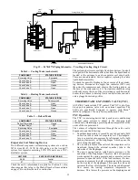
Fig. 19 — 547K 07N Piping Schematic — Two-Stage Cooling, Single Circuit
Evaporator Coil Metering Devices
Two different evaporator coil metering systems are used on
547K sizes 04-07. 547K 04-06A units use the Acutrol™
system for evaporator metering. 547K 07N units use a TXV-
distributer system.
Check the unit’s information data plate for Position 8 value,
then compare this value to the Model Number Nomenclature
on page 54 to confirm the unit’s construction.
The metering devices are multiple fixed-bore devices (Acutrol)
swedged into the horizontal outlet tubes from the liquid header,
located at the entrance to each evaporator coil circuit path.
These are non-adjustable. Service requires replacing the entire
liquid header assembly.
To check for possible blockage of one or more of these meter
-
ing devices, disconnect the supply fan contactor (IFC) coil,
then start the compressor and observe the frosting pattern on
the face of the evaporator coil. A frost pattern should develop
uniformly across the face of the coil starting at each horizontal
header tube. Failure to develop frost at an outlet tube can indi
-
cate a plugged or missing orifice.
THERMOSTATIC EXPANSION VALVE (TXV)
All 547K 07 units include TXV control. The TXV is a bi
-
flow,
bleed port expansion valve with an external equalizer. The
TXVs are specifically designed to operate with Puron
®
(R410A) refrigerant. Use only factory-authorized TXVs.
TXV Operation
The TXV is a metering device that is used in air conditioning
and heat pump systems to adjust to the changing load
conditions by maintaining a preset superheat temperature at the
outlet of the evaporator coil.
The volume of refrigerant metered through the valve seat is
dependent upon the following:
1. Superheat temperature is sensed by cap tube sensing bulb
on suction tube at outlet of evaporator coil. This tempera
-
ture is converted into pressure by refrigerant in the bulb
pushing downward on the diaphragm, which opens the
valve using the push rods.
2. The suction pressure at the outlet of the evaporator coil is
transferred through the external equalizer tube to the
underside of the diaphragm.
3. The pin is spring loaded, which exerts pressure on the
underside of the diaphragm. Therefore, the bulb pressure
works against the spring pressure and evaporator suction
pressure to open the valve. If the load increases, the tem
-
perature increases at the bulb, which increases the pressure
on the top side of the diaphragm. This opens the valve and
increases the flow of refrigerant. The increased refrigerant
flow causes the leaving evaporator temperature to
decrease. This lowers the pressure on the diaphragm and
B
Acutrol
DFT 1
Cooling Liquid Line
A
D
Outdoor Coil
Indoor Coil
C
Heating Mode Liquid Line
Strainer
Filter
Drier
LPS/LOC
Accurater
TXV
COMPRESSOR
ACCUMULATOR
HPS
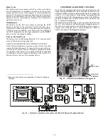
Table 3 — Cooling Mode (each circuit)
COMPONENT
STATUS/POSITION
Reversing Valve
Energized
Check Valve A
Closed
Check Valve B
Open
Check Valve C
Closed
Check Valve D
Open
Table 4 — Heating Mode (each circuit)
COMPONENT
STATUS/POSITION
Reversing Valve
De-energized
Check Valve A
Open
Check Valve B
Closed
Check Valve C
Open
Check Valve D
Closed
Table 5 — Defrost Mode
COMPONENT
STATUS/POSITION
Defrost Thermostat
Closed
Outdoor Fan(s)
Off
Reversing Valve
Energized
Check Valve A
Closed
Check Valve B
Open
Check Valve C
Closed
Check Valve D
Open
UNIT SIZE
EVAPORATOR METERING
04-06
Acutrol
07
TXV
Содержание 547K
Страница 94: ...94 APPENDIX D WIRING DIAGRAMS Fig I 547K 04 06 Power Wiring Diagram 208 230 1 60 ...
Страница 95: ...95 APPENDIX D WIRING DIAGRAMS Fig J 547K 04 07 Power Wiring Diagram 208 230 3 60 ...
Страница 96: ...96 APPENDIX D WIRING DIAGRAMS Fig K 5047K 04 07 Power Wiring Diagram 460 575 3 60 ...


