10
Clean coil as follows:
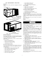
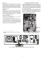
1. Turn off unit power, tag disconnect.
2. Remove all screws from the top panel except the screws
securing the condenser fan to the top panel. See Fig. 14.
Fig. 14 — Location of Screws and Coil Corner Post
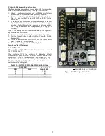
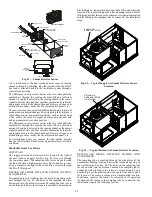
3. Lift and rotate the top panel at the condenser fan end and
rotate the panel 90 degrees. Support the top panel so it
remains level while resting on the condenser fan as shown
in Fig. 15.
Fig. 15 — Top Panel Position
4. Remove the compressor access panel to access the lower coil
clip. The condenser coil corner post may also be removed.
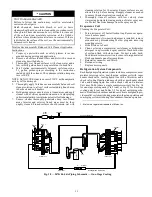
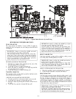
5. Remove the screws from both sides of the upper and lower
coil retaining clips on the hairpin end of the coil tube
sheets. See Fig. 16.
6. Remove the upper and lower retaining clips.
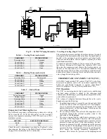
7. Draw the inner coil inward to separate the coils for cleaning.
8. Insert a spacer (field-supplied) between the tube sheets to
hold the coils apart. See Fig. 17.
9. Clean the outer coil surface to remove surface loaded fibers
or dirt. See “Remove Surface Loaded Fibers” on page 9 for
details.
10. Use a water hose or other suitable equipment to flush
down between the 2 coil sections to remove dirt and
debris. If a coil cleaner is used be sure to rinse the coils
completely before reassembly.
11. Move the inner coil back into position. Reinstall the lower
and upper coil clips. Reinstall the top panel and replace all
screws.
Fig. 16 — Condenser Coil Clips
Fig. 17 — Separating Coil Sections
Totaline Environmentally Balanced Coil Cleaner Application
Equipment
• 2
1
/
2
gallon garden sprayer
• Water rinse with low velocity spray nozzle
TOP PANEL
REMOVE SCREWS
FROM ALL SIDES
OF TOP PANEL
REMOVE
SCREWS
CONDENSER
FAN
CONDENSER
COIL
CONDENSER COIL
CORNER POST
CENTER
POST
COMPRESSOR
ACCESS PANEL
TOP PANEL
CENTER
BAFFLE
COMPRESSOR
ACCESS
PANEL
SUPPORT
(FIELD-SUPPLIED)
CAUTION
UNIT DAMAGE HAZARD
Failure to follow this caution may result in reduced unit
performance or unit shutdown.
High velocity water from a pressure washer, garden hose,
or compressed air should never be used to clean a coil. The
force of the water or air jet will bend the fin edges and
increase airside pressure drop.
COIL CLIPS
102 mm
(4" MAX)
INNER
COIL
SECTION
OUTER
COIL
SECTION
CONDENSER
COIL
CENTER BAFFLE
HAIRPIN
END
TOP VIEW
SPACER
(FIELD-SUPPLIED)
Содержание 547K
Страница 94: ...94 APPENDIX D WIRING DIAGRAMS Fig I 547K 04 06 Power Wiring Diagram 208 230 1 60 ...
Страница 95: ...95 APPENDIX D WIRING DIAGRAMS Fig J 547K 04 07 Power Wiring Diagram 208 230 3 60 ...
Страница 96: ...96 APPENDIX D WIRING DIAGRAMS Fig K 5047K 04 07 Power Wiring Diagram 460 575 3 60 ...


