VPSB-DC and VPSB-DC-E
H172203_1_001
175 / 234
15.4.6
Front Panel - Connectors and LED‘s
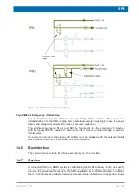
All interfaces for both the VPSB-DC and the VPSB-DC-E are the same.
Figure 15.4: Front View of a VPSB-DC
Error LED
This LED is lit after power ON. It turns off as soon as the VPSB-DC(-E) is initialized (i.e. the
FPGA has loaded its configuration from the flash memory and the communication with the
ELCB is established).
Later on, an active Error LED indicates that an error has occurred (e. g. short circuit,
watchdog event,...) and that in consequence the connected VTAs and the power outputs are
switched off.
Содержание NMR AV4 BSMS System
Страница 1: ...BSMS System for AVANCE NEO User Manual Version 001 Innovation with Integrity NMR...
Страница 10: ...Contents x H172203_1_001...
Страница 22: ...Safety 22 234 H172203_1_001...
Страница 26: ...Transport Packaging and Storage 26 234 H172203_1_001...
Страница 42: ...Chassis Mainframe 42 234 H172203_1_001...
Страница 46: ...Fan Tray 46 234 H172203_1_001...
Страница 55: ...ELCB H172203_1_001 55 234 Figure 8 1 ELCB Front Panel with LED s and Connectors...
Страница 69: ...ELCB H172203_1_001 69 234 Figure 8 13 Lock RF Boards Diagnostics...
Страница 70: ...ELCB 70 234 H172203_1_001...
Страница 120: ...L TRX L 19F 120 234 H172203_1_001...
Страница 128: ...BSVT Introduction Configurations 128 234 H172203_1_001 12 8 2 HR RT Probes BTO2000 Figure 12 6 HR RT Probes BTO2000...
Страница 148: ...BSVT Concept 148 234 H172203_1_001...
Страница 151: ...SPB H172203_1_001 151 234 14 4 System Architecture Overview Figure 14 1 Block Diagram of the SPB...
Страница 166: ...SPB 166 234 H172203_1_001...
Страница 171: ...VPSB DC and VPSB DC E H172203_1_001 171 234 15 4 System Architecture Overview Figure 15 2 Block Diagram of the VPSB DC...
Страница 172: ...VPSB DC and VPSB DC E 172 234 H172203_1_001 Figure 15 3 Block Diagram of the VPSB DC E...
Страница 180: ...VPSB DC and VPSB DC E 180 234 H172203_1_001...
Страница 187: ...VTA H172203_1_001 187 234 Figure 16 1 VTA Cable Connectors...
Страница 193: ...VTA H172203_1_001 193 234 16 7 Ordering Information See Basic BSVT Configuration 124...
Страница 194: ...VTA 194 234 H172203_1_001...
Страница 200: ...Nitrogen Level Sensor 200 234 H172203_1_001...
Страница 204: ...Radiation Shield Temperature Monitoring MAG RS 204 234 H172203_1_001...
Страница 208: ...Installation and Initial Commissioning 208 234 H172203_1_001...
Страница 210: ...Operation 210 234 H172203_1_001...
Страница 216: ...Replacement of Parts 216 234 H172203_1_001...
Страница 222: ...Contact 222 234 H172203_1_001...
Страница 226: ...List of Figures 226 234 H172203_1_001...
Страница 229: ...Glossary H172203_1_001 229 234 Glossary...
Страница 230: ...Glossary 230 234 H172203_1_001...
Страница 232: ...Index 232 234 H172203_1_001...
Страница 233: ...H172203_1_001 233 234...
Страница 234: ...Bruker Corporation info bruker com www bruker com Order No H172203...


