L-TRX/L-19F
H172203_1_001
97 / 234
11.2.1
Function Description
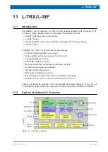
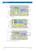
The architecture of the L-TRX / L-19F units is significantly different to the design of the former
L-TX and L-RX units. The individual signal processing and amplifier control stages are as
much as possible shifted into the digital domain.
Signal processing
The transmitter consists of a direct digital synthesizer. The output power range is fully
implemented with D/A-converters, which eliminates the need of real-time controlled analog
attenuators.
The receiver consists of a mostly direct digital system. The receiver gain is mainly
implemented in the digital section.
Deuterium Power Amplifier with Active Quiescent Current Control
The operating point of the on-board 5W power amplifier for 2H gradient shimming is matched
to the different operating modes in order to reduce power dissipation. The individual
quiescent current values are stored in the calibration data memory of each unit. In
2H Lock
mode the quiescent current is actively regulated.
Gradient Shimming
Together with the L-19F unit, the on-board 5W power amplifier should not be used for
gradient shimming on 2H. In spectrometer configurations with the L-19F unit a high power 2H
amplifier is anyway mandatory for 2H observe experiments. In this configuration the same
high power 2H amplifier is used for gradient shimming.
The L-TRX / L-19F units do not support gradient shimming on 19F.
Reference Clock
The L-TRX / L-19F units requires a reference frequency mixture produced by the AV4
REFERENCE board. The former 10 MHz system clock is not required anymore.
SSRB Communication Interface with ELCB
The L-TRX / L-19F units use a dedicated SSRB (Synchronous Serial Rack Bus) interface for
control and data transfer to the ELCB.
Real-Time Pulses via Backplane
The L-TRX is able to receive and transmit real-time control pulses via backplane to reduce
external wiring. This feature is currently only used in the NanoBay console (BLNKTR_2H~).
Other pulses and/or consoles may follow in the future.
2H-TR Power Amplifier Output Connector
The output connector is a N-type instead of SMA to avoid the risk of unintentional wrong
wiring. E.g. low power RF-boards could be permanently damaged if wrongfully connected to
the 5W power output of the L-TRX.
Содержание NMR AV4 BSMS System
Страница 1: ...BSMS System for AVANCE NEO User Manual Version 001 Innovation with Integrity NMR...
Страница 10: ...Contents x H172203_1_001...
Страница 22: ...Safety 22 234 H172203_1_001...
Страница 26: ...Transport Packaging and Storage 26 234 H172203_1_001...
Страница 42: ...Chassis Mainframe 42 234 H172203_1_001...
Страница 46: ...Fan Tray 46 234 H172203_1_001...
Страница 55: ...ELCB H172203_1_001 55 234 Figure 8 1 ELCB Front Panel with LED s and Connectors...
Страница 69: ...ELCB H172203_1_001 69 234 Figure 8 13 Lock RF Boards Diagnostics...
Страница 70: ...ELCB 70 234 H172203_1_001...
Страница 120: ...L TRX L 19F 120 234 H172203_1_001...
Страница 128: ...BSVT Introduction Configurations 128 234 H172203_1_001 12 8 2 HR RT Probes BTO2000 Figure 12 6 HR RT Probes BTO2000...
Страница 148: ...BSVT Concept 148 234 H172203_1_001...
Страница 151: ...SPB H172203_1_001 151 234 14 4 System Architecture Overview Figure 14 1 Block Diagram of the SPB...
Страница 166: ...SPB 166 234 H172203_1_001...
Страница 171: ...VPSB DC and VPSB DC E H172203_1_001 171 234 15 4 System Architecture Overview Figure 15 2 Block Diagram of the VPSB DC...
Страница 172: ...VPSB DC and VPSB DC E 172 234 H172203_1_001 Figure 15 3 Block Diagram of the VPSB DC E...
Страница 180: ...VPSB DC and VPSB DC E 180 234 H172203_1_001...
Страница 187: ...VTA H172203_1_001 187 234 Figure 16 1 VTA Cable Connectors...
Страница 193: ...VTA H172203_1_001 193 234 16 7 Ordering Information See Basic BSVT Configuration 124...
Страница 194: ...VTA 194 234 H172203_1_001...
Страница 200: ...Nitrogen Level Sensor 200 234 H172203_1_001...
Страница 204: ...Radiation Shield Temperature Monitoring MAG RS 204 234 H172203_1_001...
Страница 208: ...Installation and Initial Commissioning 208 234 H172203_1_001...
Страница 210: ...Operation 210 234 H172203_1_001...
Страница 216: ...Replacement of Parts 216 234 H172203_1_001...
Страница 222: ...Contact 222 234 H172203_1_001...
Страница 226: ...List of Figures 226 234 H172203_1_001...
Страница 229: ...Glossary H172203_1_001 229 234 Glossary...
Страница 230: ...Glossary 230 234 H172203_1_001...
Страница 232: ...Index 232 234 H172203_1_001...
Страница 233: ...H172203_1_001 233 234...
Страница 234: ...Bruker Corporation info bruker com www bruker com Order No H172203...


