SPB
H172203_1_001
157 / 234
14.5.2
Analog Liquid Nitrogen Level Measurement (SPB-E only)
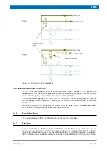
Nitrogen level measurements are performed by a sensor that is encircled by a cylindrical
conductor. The sensor and surrounding conductor form a capacitor. The presence of liquid
nitrogen between the sensor and conductor changes the capacitance, and this is measured
and converted by the sensor electronics into a proportional voltage which is interpreted by the
SPB-E to provide the reading.
The measurement circuit on the SPB-E board is separated galvanically from the other
electronics.
The interface of the SPB-E is fully compatible with all models of Bruker
.
It is recommended to use the digital nitrogen level sensor and connect it to the AUX port of
the SPB-E or the VPSB(-DC). For details see
.
14.5.3
Sample Down and Sample Up Detection
The interface for standard Bruker Shim Upper part (BST) is backward compatible to the
former SLCB circuit. An improved signal processing for the sample down detection allows
reliable detection of the various spinners. Sensor supplies are short circuit proof and wiring
detection allows improved system diagnostic.
14.5.4
Version of the Shim Upper Part
The shim upper part version can be read by the SPB.
Old style shim upper parts (SOT72) using Z12084 CABLE ADAPT BSMS/SOT72 can be
connected to a SPB(-E) ECL02.03 and newer. Because these shim upper parts do not
include a sample up light barrier, reduced functionality (sample lift speed, display) will result.
14.5.5
Sample Changer Interface
The sample changer has its own pneumatic controller. The shim upper part (BST) is
equipped with a light switch to detect whether there is a sample present for pickup. This
information is then passed to the sample changer via the sample changer interface of the
BSMS.
14.5.6
Control Output for BSMS/2 Variable Power Supply Board
The SPB provides 1 (SPB) or 2 (SPB-E) interfaces for connecting BSMS/2 VARIABLE
POWER SUPPLY BOARDS (VPSB). These boards do not have any connections to the
BSMS backplane and all control signals are carried over this interface.
On the interface connector some supply and detection signals and a high speed LVDS-
based digital interface are wired. The LVDS-based interface carries the Synchronous Serial
Rack Bus signals from the ELCB and BSMS backplane over the cable connection to the
control FPGA on the VPSB. The interface is hot-plug capable, has automatic connect/
disconnect detection and power supply signals are short-circuit proof.
Note: The new AV4 VPSB-DC(-E) does not require this interface connector.
Содержание NMR AV4 BSMS System
Страница 1: ...BSMS System for AVANCE NEO User Manual Version 001 Innovation with Integrity NMR...
Страница 10: ...Contents x H172203_1_001...
Страница 22: ...Safety 22 234 H172203_1_001...
Страница 26: ...Transport Packaging and Storage 26 234 H172203_1_001...
Страница 42: ...Chassis Mainframe 42 234 H172203_1_001...
Страница 46: ...Fan Tray 46 234 H172203_1_001...
Страница 55: ...ELCB H172203_1_001 55 234 Figure 8 1 ELCB Front Panel with LED s and Connectors...
Страница 69: ...ELCB H172203_1_001 69 234 Figure 8 13 Lock RF Boards Diagnostics...
Страница 70: ...ELCB 70 234 H172203_1_001...
Страница 120: ...L TRX L 19F 120 234 H172203_1_001...
Страница 128: ...BSVT Introduction Configurations 128 234 H172203_1_001 12 8 2 HR RT Probes BTO2000 Figure 12 6 HR RT Probes BTO2000...
Страница 148: ...BSVT Concept 148 234 H172203_1_001...
Страница 151: ...SPB H172203_1_001 151 234 14 4 System Architecture Overview Figure 14 1 Block Diagram of the SPB...
Страница 166: ...SPB 166 234 H172203_1_001...
Страница 171: ...VPSB DC and VPSB DC E H172203_1_001 171 234 15 4 System Architecture Overview Figure 15 2 Block Diagram of the VPSB DC...
Страница 172: ...VPSB DC and VPSB DC E 172 234 H172203_1_001 Figure 15 3 Block Diagram of the VPSB DC E...
Страница 180: ...VPSB DC and VPSB DC E 180 234 H172203_1_001...
Страница 187: ...VTA H172203_1_001 187 234 Figure 16 1 VTA Cable Connectors...
Страница 193: ...VTA H172203_1_001 193 234 16 7 Ordering Information See Basic BSVT Configuration 124...
Страница 194: ...VTA 194 234 H172203_1_001...
Страница 200: ...Nitrogen Level Sensor 200 234 H172203_1_001...
Страница 204: ...Radiation Shield Temperature Monitoring MAG RS 204 234 H172203_1_001...
Страница 208: ...Installation and Initial Commissioning 208 234 H172203_1_001...
Страница 210: ...Operation 210 234 H172203_1_001...
Страница 216: ...Replacement of Parts 216 234 H172203_1_001...
Страница 222: ...Contact 222 234 H172203_1_001...
Страница 226: ...List of Figures 226 234 H172203_1_001...
Страница 229: ...Glossary H172203_1_001 229 234 Glossary...
Страница 230: ...Glossary 230 234 H172203_1_001...
Страница 232: ...Index 232 234 H172203_1_001...
Страница 233: ...H172203_1_001 233 234...
Страница 234: ...Bruker Corporation info bruker com www bruker com Order No H172203...


