SCB20
78 / 234
H172203_1_001
2
Some BOSS files provide more than one mode, which can be selected here.
However, it is no longer necessary to differentiate between US and non-US
systems, install mode and user mode. Typically, one mode is sufficient.
3
Here is the identification of the connected Shim System, which is based on 2
(BOSS1) or 3 hardware codes.
4
The maximum power dissipated in the Shim System - this value is defined in the
BOSS file.
5
For specific situations it is possible to adapt/extend the
Shim Power Limit
.
Setting this flag to
yes
allows to override the value of the BOSS file by a user
specific limit (service account necessary) -> the value can then be entered under
point 4.
6
Time in seconds for softly starting up / shutting down the Shim Subsystem.
7
Normally the TopSpin application makes sure that there is an appropriate BOSS
file loaded - it can be however necessary to do this manually. This menu point
provides selecting a specific BOSS file and loading it to the BSMS. The BOSS file
is handled by the ELCB firmware - if the file is not valid (e. g. syntax errors,
missing definitions), the Logging can be checked for details (kind of error, line
number of the BOSS file where the error has been detected).
9.5.3
View and Modify the Shims
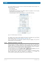
Figure 9.6: View and Manual Modification of the Shims
The example in the diagram above shows a Shim Subsystem configured for 28 available/
accessible Shims. By the small panel at the bottom, the selected Shim (
Z
in our example) can
be viewed or modified manually.
Содержание NMR AV4 BSMS System
Страница 1: ...BSMS System for AVANCE NEO User Manual Version 001 Innovation with Integrity NMR...
Страница 10: ...Contents x H172203_1_001...
Страница 22: ...Safety 22 234 H172203_1_001...
Страница 26: ...Transport Packaging and Storage 26 234 H172203_1_001...
Страница 42: ...Chassis Mainframe 42 234 H172203_1_001...
Страница 46: ...Fan Tray 46 234 H172203_1_001...
Страница 55: ...ELCB H172203_1_001 55 234 Figure 8 1 ELCB Front Panel with LED s and Connectors...
Страница 69: ...ELCB H172203_1_001 69 234 Figure 8 13 Lock RF Boards Diagnostics...
Страница 70: ...ELCB 70 234 H172203_1_001...
Страница 120: ...L TRX L 19F 120 234 H172203_1_001...
Страница 128: ...BSVT Introduction Configurations 128 234 H172203_1_001 12 8 2 HR RT Probes BTO2000 Figure 12 6 HR RT Probes BTO2000...
Страница 148: ...BSVT Concept 148 234 H172203_1_001...
Страница 151: ...SPB H172203_1_001 151 234 14 4 System Architecture Overview Figure 14 1 Block Diagram of the SPB...
Страница 166: ...SPB 166 234 H172203_1_001...
Страница 171: ...VPSB DC and VPSB DC E H172203_1_001 171 234 15 4 System Architecture Overview Figure 15 2 Block Diagram of the VPSB DC...
Страница 172: ...VPSB DC and VPSB DC E 172 234 H172203_1_001 Figure 15 3 Block Diagram of the VPSB DC E...
Страница 180: ...VPSB DC and VPSB DC E 180 234 H172203_1_001...
Страница 187: ...VTA H172203_1_001 187 234 Figure 16 1 VTA Cable Connectors...
Страница 193: ...VTA H172203_1_001 193 234 16 7 Ordering Information See Basic BSVT Configuration 124...
Страница 194: ...VTA 194 234 H172203_1_001...
Страница 200: ...Nitrogen Level Sensor 200 234 H172203_1_001...
Страница 204: ...Radiation Shield Temperature Monitoring MAG RS 204 234 H172203_1_001...
Страница 208: ...Installation and Initial Commissioning 208 234 H172203_1_001...
Страница 210: ...Operation 210 234 H172203_1_001...
Страница 216: ...Replacement of Parts 216 234 H172203_1_001...
Страница 222: ...Contact 222 234 H172203_1_001...
Страница 226: ...List of Figures 226 234 H172203_1_001...
Страница 229: ...Glossary H172203_1_001 229 234 Glossary...
Страница 230: ...Glossary 230 234 H172203_1_001...
Страница 232: ...Index 232 234 H172203_1_001...
Страница 233: ...H172203_1_001 233 234...
Страница 234: ...Bruker Corporation info bruker com www bruker com Order No H172203...


