


VTA
H172203_1_001
189 / 234
CryoProbe Adaptation (VTA CRP)
In contrast to the room temperature probes the CryoProbes use PT100 sensors for both
regulator and safety temperature measurement. Their heater impedance is higher than that of
a room temperature probe.
Furthermore, the analog signal from the safety sensor must be wired to the CryoPlatform
which also delivers the bias current. This ‘lending-out’ of the safety sensor establishes a
redundant system for sample temperature monitoring. To prevent ground coupling, the
signals between the BSMS and the CryoPlatform are galvanically isolated. If the
CryoPlatform is switched off, the VTA is unable to measure the safety sensor and thus
inhibits sample heating.
Care must be taken when connecting the CryoPlatform: The male connector on the
CryoPlatform side exposes a voltage of about 29 V on a pin. It is almost impossible to plug
the VTA cable without shorting this pin to frame ground which can damage the CRCO and
the VTA. Always switch off the CryoPlatform when connecting the VTA CRP to its rear panel!
The VTA can be left connected to CryoPlatform and must not be disconnected when
operating a RT probe.
BCU-05 and BCU-X Adaptation (VTA BCU)
To integrate the legacy BCU gas chillers into the new temperature system an adaptor VTA is
needed. It detects the presence of such a chiller and enables remote operation.
The VTA BCU can be used for BCU05 or BCU-X (BCU-Extreme) type of cooling units and
can be connected to an auxiliary control port.
New BCU I and BCU II do not need a VTA BCU adapter. They come with an embedded VTA-
style interface and should be connected to an auxiliary control port.
Adaptation of Low Temperature Options (VTA LN2)
For sample temperature control far below room temperature two devices are available: the
LN2 Heat Exchanger and the LN2 Evaporator.
The VTA LN2 adapts both and detects the type of the connected device. It monitors the level
and safety sensors and continuously sends these values to the BSMS/2 ELCB where they
are evaluated.
For LN2 Heat Exchanger and LN2 Evaporator operation heater power is required. The heater
power is fed through the VTA and the heater safety sensor is monitored for safe operation.
For that an additional heater cable is necessary (Z116301 CABLE RD 15P 4.5M 1:1 BSMS/2
VPSB-VTA or Z116304 CABLE RD 15P 9M 1:1 BSMS/2 VPSB-VTA).
16.4.1
Protection
All external interfaces are protected against short circuits. The monitoring takes place on the
VPSB board (measurement electronics) and on the ELCB board (monitoring of low level
measurements from the VPSB board).
Monitored are:
• Heater and controller temperature
• Heater -voltage and -current
• Impedance of connected devices (e.g. heater)
• Communication between VTA and VPSB
Supervision is done via status information.
If one of the measurements is outside the tolerance, the BSVT and all connected devices will
switch off.
Содержание NMR AV4 BSMS System
Страница 1: ...BSMS System for AVANCE NEO User Manual Version 001 Innovation with Integrity NMR...
Страница 10: ...Contents x H172203_1_001...
Страница 22: ...Safety 22 234 H172203_1_001...
Страница 26: ...Transport Packaging and Storage 26 234 H172203_1_001...
Страница 42: ...Chassis Mainframe 42 234 H172203_1_001...
Страница 46: ...Fan Tray 46 234 H172203_1_001...
Страница 55: ...ELCB H172203_1_001 55 234 Figure 8 1 ELCB Front Panel with LED s and Connectors...
Страница 69: ...ELCB H172203_1_001 69 234 Figure 8 13 Lock RF Boards Diagnostics...
Страница 70: ...ELCB 70 234 H172203_1_001...
Страница 120: ...L TRX L 19F 120 234 H172203_1_001...
Страница 128: ...BSVT Introduction Configurations 128 234 H172203_1_001 12 8 2 HR RT Probes BTO2000 Figure 12 6 HR RT Probes BTO2000...
Страница 148: ...BSVT Concept 148 234 H172203_1_001...
Страница 151: ...SPB H172203_1_001 151 234 14 4 System Architecture Overview Figure 14 1 Block Diagram of the SPB...
Страница 166: ...SPB 166 234 H172203_1_001...
Страница 171: ...VPSB DC and VPSB DC E H172203_1_001 171 234 15 4 System Architecture Overview Figure 15 2 Block Diagram of the VPSB DC...
Страница 172: ...VPSB DC and VPSB DC E 172 234 H172203_1_001 Figure 15 3 Block Diagram of the VPSB DC E...
Страница 180: ...VPSB DC and VPSB DC E 180 234 H172203_1_001...
Страница 187: ...VTA H172203_1_001 187 234 Figure 16 1 VTA Cable Connectors...
Страница 193: ...VTA H172203_1_001 193 234 16 7 Ordering Information See Basic BSVT Configuration 124...
Страница 194: ...VTA 194 234 H172203_1_001...
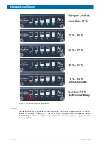
Страница 200: ...Nitrogen Level Sensor 200 234 H172203_1_001...
Страница 204: ...Radiation Shield Temperature Monitoring MAG RS 204 234 H172203_1_001...
Страница 208: ...Installation and Initial Commissioning 208 234 H172203_1_001...
Страница 210: ...Operation 210 234 H172203_1_001...
Страница 216: ...Replacement of Parts 216 234 H172203_1_001...
Страница 222: ...Contact 222 234 H172203_1_001...
Страница 226: ...List of Figures 226 234 H172203_1_001...
Страница 229: ...Glossary H172203_1_001 229 234 Glossary...
Страница 230: ...Glossary 230 234 H172203_1_001...
Страница 232: ...Index 232 234 H172203_1_001...
Страница 233: ...H172203_1_001 233 234...
Страница 234: ...Bruker Corporation info bruker com www bruker com Order No H172203...


