


L-TRX/L-19F
H172203_1_001
99 / 234
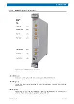
11.2.4
Technical Data BSMS/2 Lock Transceiver
Transmitter (TX):
Output power for gradient shimming @ +4 dBm input
power
Conditions: pulsed power only, max. pulse length = 1s,
max. duty-cycle = 10 %, all independent of actual output
power
min. 5
W
Output power for Lock operation:
FFA Mode (250µs pulse)
typ. 28
dBm
Lock Mode (Lock pulse)
-60...+20
dBm
Output power resolution
typ. 0.1
dB
Frequency resolution
≤ 14
mHz
Phase resolution
≤ 0.1
°(deg)
Phase range
0..360 endless
°(deg)
Frequency range
f2H ± 1
MHz
Load mismatch:
no damage
infinite
VSWR
for on board diagnostics
≤ 3.6
VSWR
Confamp (except for Z109887 and Z109888 with ECL< 2)
Supported
Receiver (RX):
Gain range
80
dB
Gain resolution
0.1
dB
Содержание NMR AV4 BSMS System
Страница 1: ...BSMS System for AVANCE NEO User Manual Version 001 Innovation with Integrity NMR...
Страница 10: ...Contents x H172203_1_001...
Страница 22: ...Safety 22 234 H172203_1_001...
Страница 26: ...Transport Packaging and Storage 26 234 H172203_1_001...
Страница 42: ...Chassis Mainframe 42 234 H172203_1_001...
Страница 46: ...Fan Tray 46 234 H172203_1_001...
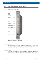
Страница 55: ...ELCB H172203_1_001 55 234 Figure 8 1 ELCB Front Panel with LED s and Connectors...
Страница 69: ...ELCB H172203_1_001 69 234 Figure 8 13 Lock RF Boards Diagnostics...
Страница 70: ...ELCB 70 234 H172203_1_001...
Страница 120: ...L TRX L 19F 120 234 H172203_1_001...
Страница 128: ...BSVT Introduction Configurations 128 234 H172203_1_001 12 8 2 HR RT Probes BTO2000 Figure 12 6 HR RT Probes BTO2000...
Страница 148: ...BSVT Concept 148 234 H172203_1_001...
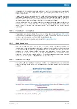
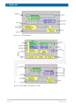
Страница 151: ...SPB H172203_1_001 151 234 14 4 System Architecture Overview Figure 14 1 Block Diagram of the SPB...
Страница 166: ...SPB 166 234 H172203_1_001...
Страница 171: ...VPSB DC and VPSB DC E H172203_1_001 171 234 15 4 System Architecture Overview Figure 15 2 Block Diagram of the VPSB DC...
Страница 172: ...VPSB DC and VPSB DC E 172 234 H172203_1_001 Figure 15 3 Block Diagram of the VPSB DC E...
Страница 180: ...VPSB DC and VPSB DC E 180 234 H172203_1_001...
Страница 187: ...VTA H172203_1_001 187 234 Figure 16 1 VTA Cable Connectors...
Страница 193: ...VTA H172203_1_001 193 234 16 7 Ordering Information See Basic BSVT Configuration 124...
Страница 194: ...VTA 194 234 H172203_1_001...
Страница 200: ...Nitrogen Level Sensor 200 234 H172203_1_001...
Страница 204: ...Radiation Shield Temperature Monitoring MAG RS 204 234 H172203_1_001...
Страница 208: ...Installation and Initial Commissioning 208 234 H172203_1_001...
Страница 210: ...Operation 210 234 H172203_1_001...
Страница 216: ...Replacement of Parts 216 234 H172203_1_001...
Страница 222: ...Contact 222 234 H172203_1_001...
Страница 226: ...List of Figures 226 234 H172203_1_001...
Страница 229: ...Glossary H172203_1_001 229 234 Glossary...
Страница 230: ...Glossary 230 234 H172203_1_001...
Страница 232: ...Index 232 234 H172203_1_001...
Страница 233: ...H172203_1_001 233 234...
Страница 234: ...Bruker Corporation info bruker com www bruker com Order No H172203...


