


APPENDIX 3 FIRMWARE SWITCHS (WSW)
A-38
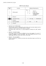
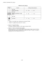
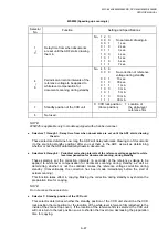
WSW36 (Function setting 14)
Selector
No.
Function
Setting and Specifications
1
ECP* mode
0: ON
1:
OFF
2
Recovery from inactive PC
interface
0:
Disabled
1:
Enabled
3
PC power-off recognition time
0: Normal
1:
Long
4 Not
used.
5
Escape from phase C
0: Yes
1:
No
6
|
8
Lower limit of frequency to be
ignored after detection of calling
signals (Ci)
No. 6 7 8
0 0 0 :
0
(Not
ignored)
0 0 1 :
4
(448
Hz)
0 1 0 :
8
(244
Hz)
0 1 1 :
12
(162
Hz)
1 0 0 :
16
(122
Hz)
1 0 1 :
20
(97
Hz)
1 1 0 :
24
(81
Hz)
1 1 1 :
28
(69
Hz)
*ECP (Enhanced Capabilities Port)
l
Selector 1: ECP mode
The ECP mode enhances the normal bidirectional communications between the machine
and the connected PC for higher transmission speed.
l
Selector 2: Recovery from inactive PC interface
If the machine recognizes via the STB signal line that the connected PC is powered off, it will
turn the PC interface outputs Low to protect the PC from hazards that could be caused by
weak electric current accidentally flown from the machine.
This selector determines whether the machine should recover from the inactive PC interface
to normal interfacing state upon receipt of data from the PC.
l
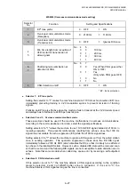
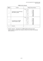
Selector 3: PC power-off recognition time
This selector sets the time length from when the machine detects the PC powered off until it
recognizes the detected state as power-off.
If selector 2 is set to "0," it is recommended that selector 3 be set to "1": otherwise, the
machine may mistakenly detect PC powered off.
l
Selector 5: Escape from phase C
This selector determines whether or not the machine will escape from phase C when it
detects an RTC (Return to Control) in non-ECM mode or an RCP (Return to Control Partial
page) in ECM mode.
l
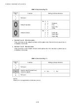
Selectors 6 through 8: Lower limit of frequency to be ignored after detection of calling signals
(Ci)
At the start of reception, if the machine detects the frequency of calling signals (Ci) specified
by selectors 1 through 4 of WSW14, it will start the ringer sounding. When doing so, the
machine may fail to detect the calling signals normally due to noises superimposed at the
time of reception. To prevent it, use selectors 6 through 8 of WSW36.
If the machine detects higher frequencies than the lower limit specified by these selectors, it
will regard them as noise and interpret that detecting state as being normal, allowing the
ringer to keep sounding (until the machine starts automatic reception of FAX data if in the
FAX mode, according to the preset number of ringers).
Содержание DCP-8040
Страница 146: ...CHAPTER 4 DISASSEMBLY AND RE ASSEMBLY 4 64 5 Remove the shutter arm C Fig 4 115 Shutter arm C Frame L ...
Страница 276: ...CHAPTER 7 MAINTENANCE MODE 7 6 Fig 7 3 l m a b c d e f g h i j k ...
Страница 347: ...APPENDIX 4 CIRCUIT DIAGRAMS A 50 Appendix 4 1 Main PCB Circuit Diagram 1 7 ...
Страница 348: ...MFC 8440 8840D 8840DN DCP 8040 8045D 8045DN SERVICE MANUAL A 51 Appendix 4 2 Main PCB Circuit Diagram 2 7 ...
Страница 349: ...APPENDIX 4 CIRCUIT DIAGRAMS A 52 Appendix 4 3 Main PCB Circuit Diagram 3 7 ...
Страница 350: ...MFC 8440 8840D 8840DN DCP 8040 8045D 8045DN SERVICE MANUAL A 53 Appendix 4 4 Main PCB Circuit Diagram 4 7 ...
Страница 351: ...APPENDIX 4 CIRCUIT DIAGRAMS A 54 Appendix 4 5 Main PCB Circuit Diagram 5 7 ...
Страница 352: ...MFC 8440 8840D 8840DN DCP 8040 8045D 8045DN SERVICE MANUAL A 55 Appendix 4 6 Main PCB Circuit Diagram 6 7 ...
Страница 353: ...APPENDIX 4 CIRCUIT DIAGRAMS A 56 Appendix 4 7 Main PCB Circuit Diagram 7 7 ...
Страница 354: ...MFC 8440 8840D 8840DN DCP 8040 8045D 8045DN SERVICE MANUAL A 57 Appendix 4 8 Driver PCB Circuit Diagram ...
Страница 355: ...APPENDIX 4 CIRCUIT DIAGRAMS A 58 Appendix 4 9 Engine PCB Circuit Diagram 1 2 ...
Страница 356: ...MFC 8440 8840D 8840DN DCP 8040 8045D 8045DN SERVICE MANUAL A 59 Appendix 4 10 Engine PCB Circuit Diagram 2 2 ...
Страница 357: ...APPENDIX 4 CIRCUIT DIAGRAMS A 60 Appendix 4 11 NCU PCB Circuit Diagram U S A ...
Страница 358: ...MFC 8440 8840D 8840DN DCP 8040 8045D 8045DN SERVICE MANUAL A 61 Appendix 4 12 NCU PCB Circuit Diagram Europe ...
Страница 359: ...APPENDIX 4 CIRCUIT DIAGRAMS A 62 Appendix 4 13 NCU PCB Circuit Diagram Asia ...
Страница 360: ...MFC 8440 8840D 8840DN DCP 8040 8045D 8045DN SERVICE MANUAL A 63 Appendix 4 14 NCU PCB Circuit Diagram Oceania ...
Страница 361: ...APPENDIX 4 CIRCUIT DIAGRAMS A 64 Appendix 4 15 Control Panel PCB Circuit Diagram ...
Страница 363: ...APPENDIX 4 CIRCUIT DIAGRAMS A 66 Appendix 4 17 Low voltage Power Supply PCB Circuit Diagram 100V ...
Страница 365: ...APPENDIX 4 CIRCUIT DIAGRAMS A 68 Appendix 4 19 High voltage Power Supply PCB Circuit Diagram 100V ...
Страница 367: ...April 04 SM FAX027 5 8C5903 Printed in Japan ...