


CHAPTER 6 TROUBLESHOOTING
6-24
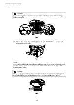
WARNING
If you analyze malfunctions with the power plug inserted into the power outlet, special
caution should be exercised even if the power switch is OFF because it is a single pole
switch.
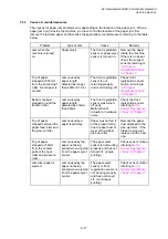
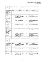
M-3
Main motor failure
Possible cause
Step
Check
Result
Remedy
Failure of
connector
1
Is the connection of connector
CN9 on the engine PCB
correct?
No
Reconnect the connector.
Main motor
2
Is the problem solved by
replacing the main motor?
Yes
Replace the main motor.
Engine PCB
3
Is the problem solved by
replacing the engine PCB?
Yes
Replace the engine PCB.
Main PCB
4
Is the problem solved by
replacing the main PCB?
Yes
Replace the main PCB.
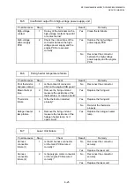
M-4
No paper supplied
Possible cause
Step
Check
Result
Remedy
Failure of
connector
1
Is the contact of the solenoid
connector on the engine PCB
good?
No
Reconnect the connector.
Engine PCB
circuit
2
Set paper in the manual paper
slot and make a test print by
pressing the control panel
button.
Yes
Replace the engine PCB.
Paper pick-up
clutch solenoid
Does the voltage between pins
2 (SOLENOID) and 1 (24V) of
the CN16 connector on the
engine PCB change from
approx. 24V DC to 0V within
the specified time?
No
Replace the paper pick-up
solenoid.
Separation pad /
pick-up roller
failure
3
Is the surface of the separation
pad or the pick-up roller dirty or
worn out?
Yes
1) Clean the surface of the
separation pad or pick-up
roller.
2) Replace the separation
pad or pick-up roller.
Main PCB
4
Is the problem solved by
replacing the main PCB?
Yes
Replace the main PCB.
Содержание DCP-8040
Страница 146: ...CHAPTER 4 DISASSEMBLY AND RE ASSEMBLY 4 64 5 Remove the shutter arm C Fig 4 115 Shutter arm C Frame L ...
Страница 276: ...CHAPTER 7 MAINTENANCE MODE 7 6 Fig 7 3 l m a b c d e f g h i j k ...
Страница 347: ...APPENDIX 4 CIRCUIT DIAGRAMS A 50 Appendix 4 1 Main PCB Circuit Diagram 1 7 ...
Страница 348: ...MFC 8440 8840D 8840DN DCP 8040 8045D 8045DN SERVICE MANUAL A 51 Appendix 4 2 Main PCB Circuit Diagram 2 7 ...
Страница 349: ...APPENDIX 4 CIRCUIT DIAGRAMS A 52 Appendix 4 3 Main PCB Circuit Diagram 3 7 ...
Страница 350: ...MFC 8440 8840D 8840DN DCP 8040 8045D 8045DN SERVICE MANUAL A 53 Appendix 4 4 Main PCB Circuit Diagram 4 7 ...
Страница 351: ...APPENDIX 4 CIRCUIT DIAGRAMS A 54 Appendix 4 5 Main PCB Circuit Diagram 5 7 ...
Страница 352: ...MFC 8440 8840D 8840DN DCP 8040 8045D 8045DN SERVICE MANUAL A 55 Appendix 4 6 Main PCB Circuit Diagram 6 7 ...
Страница 353: ...APPENDIX 4 CIRCUIT DIAGRAMS A 56 Appendix 4 7 Main PCB Circuit Diagram 7 7 ...
Страница 354: ...MFC 8440 8840D 8840DN DCP 8040 8045D 8045DN SERVICE MANUAL A 57 Appendix 4 8 Driver PCB Circuit Diagram ...
Страница 355: ...APPENDIX 4 CIRCUIT DIAGRAMS A 58 Appendix 4 9 Engine PCB Circuit Diagram 1 2 ...
Страница 356: ...MFC 8440 8840D 8840DN DCP 8040 8045D 8045DN SERVICE MANUAL A 59 Appendix 4 10 Engine PCB Circuit Diagram 2 2 ...
Страница 357: ...APPENDIX 4 CIRCUIT DIAGRAMS A 60 Appendix 4 11 NCU PCB Circuit Diagram U S A ...
Страница 358: ...MFC 8440 8840D 8840DN DCP 8040 8045D 8045DN SERVICE MANUAL A 61 Appendix 4 12 NCU PCB Circuit Diagram Europe ...
Страница 359: ...APPENDIX 4 CIRCUIT DIAGRAMS A 62 Appendix 4 13 NCU PCB Circuit Diagram Asia ...
Страница 360: ...MFC 8440 8840D 8840DN DCP 8040 8045D 8045DN SERVICE MANUAL A 63 Appendix 4 14 NCU PCB Circuit Diagram Oceania ...
Страница 361: ...APPENDIX 4 CIRCUIT DIAGRAMS A 64 Appendix 4 15 Control Panel PCB Circuit Diagram ...
Страница 363: ...APPENDIX 4 CIRCUIT DIAGRAMS A 66 Appendix 4 17 Low voltage Power Supply PCB Circuit Diagram 100V ...
Страница 365: ...APPENDIX 4 CIRCUIT DIAGRAMS A 68 Appendix 4 19 High voltage Power Supply PCB Circuit Diagram 100V ...
Страница 367: ...April 04 SM FAX027 5 8C5903 Printed in Japan ...