


CHAPTER 6 TROUBLESHOOTING
6-44
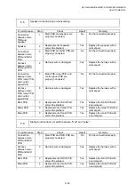
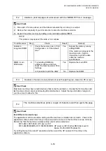
I-13 Image
distortion
Possible cause
Step
Check
Result
Remedy
Laser unit
installation
1
Is the laser unit secured to the
frame incorrectly?
(Check if there is any play.)
Yes
Secure the unit correctly and
tighten the screws.
Laser scanner
LD emission
failure
Laser scanner
motor rotation
failure
2
Is the laser diode or the
scanner motor defective?
Yes
Replace the laser unit.
Laser scanner
connection
failure
3
Is the scanner harness
connected properly?
(Check if it is coming loose.)
No
Connect the harness correctly.
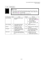
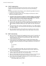
I-14 Faint
Print out test print out test print out test Print out test print o
Print out test print o
Print out test print out test print out test Print out test print o
Print out test print o
Print out test print out test print out test Print out test print o
Print out test print o
Print out test print out test print out test Print out test print o
Print out test print o
Print out test print out test print out test Print out test print o
Print out test print o
Print out test print out test print out test Print out test print o
Print out test print o
Print out test print out test print out test Print out test print o
Print out test print o
Print out test print out test print out test Print out test print o
Print out test print o
Print out test print out test print out test Print out test print o
Print out test print o
Print out test print out test print out test Print out test print o
Print out test print o
Print out test print out test print out test Print out test print o
Print out test print o
Print out test print out test print out test Print out test print o
Print out test print o
Print out test print out test print out test Print out test print o
Print out test print o
Print out test print out test print out test Print out test print o
Print out test print o
Print out test print out test print out test Print out test print o
Print out test print o
Print out test print out test print out test Print out test print o
Print out test print o
Print out test print out test print out test Print out test print o
Print out test print o
Print out test print out test print out test Print out test print o
Print out test print o
Print out test print out test print out test Print out test print o
Print out test print o
Print out test print out test print out test Print out test print o
Print out test print o
Print out test print out test print out test Print out test print o
Print out test print o
Print out test print out test print out test Print out test print o
Print out test print o
Print out test print out test print out test Print out test print o
Print out test print o
Print out test print out test print out test Print out test print o
Print out test print o
Print out test print out test print out test Print out test print o
Print out test print o
Print out test print out test print out test Print out test print o
Print out test print o
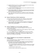
Possible cause
Step
Check
Result
Remedy
Machine
installation
1
Is the machine placed
horizontally?
No
Place the machine on a flat
surface.
Toner cartridge
2
Does the problem happen
immediately after replacing the
toner cartridge with a new
one?
Yes
Remove and carefully shake the
toner cartridge horizontally.
Scanner window
dirty
3
Is the scanner window dirty?
Yes
Clean the scanner window with a
soft dry cloth.
Laser unit failure
4
Is the problem solved by
replacing the laser unit?
Yes
Replace the laser unit.
Содержание DCP-8040
Страница 146: ...CHAPTER 4 DISASSEMBLY AND RE ASSEMBLY 4 64 5 Remove the shutter arm C Fig 4 115 Shutter arm C Frame L ...
Страница 276: ...CHAPTER 7 MAINTENANCE MODE 7 6 Fig 7 3 l m a b c d e f g h i j k ...
Страница 347: ...APPENDIX 4 CIRCUIT DIAGRAMS A 50 Appendix 4 1 Main PCB Circuit Diagram 1 7 ...
Страница 348: ...MFC 8440 8840D 8840DN DCP 8040 8045D 8045DN SERVICE MANUAL A 51 Appendix 4 2 Main PCB Circuit Diagram 2 7 ...
Страница 349: ...APPENDIX 4 CIRCUIT DIAGRAMS A 52 Appendix 4 3 Main PCB Circuit Diagram 3 7 ...
Страница 350: ...MFC 8440 8840D 8840DN DCP 8040 8045D 8045DN SERVICE MANUAL A 53 Appendix 4 4 Main PCB Circuit Diagram 4 7 ...
Страница 351: ...APPENDIX 4 CIRCUIT DIAGRAMS A 54 Appendix 4 5 Main PCB Circuit Diagram 5 7 ...
Страница 352: ...MFC 8440 8840D 8840DN DCP 8040 8045D 8045DN SERVICE MANUAL A 55 Appendix 4 6 Main PCB Circuit Diagram 6 7 ...
Страница 353: ...APPENDIX 4 CIRCUIT DIAGRAMS A 56 Appendix 4 7 Main PCB Circuit Diagram 7 7 ...
Страница 354: ...MFC 8440 8840D 8840DN DCP 8040 8045D 8045DN SERVICE MANUAL A 57 Appendix 4 8 Driver PCB Circuit Diagram ...
Страница 355: ...APPENDIX 4 CIRCUIT DIAGRAMS A 58 Appendix 4 9 Engine PCB Circuit Diagram 1 2 ...
Страница 356: ...MFC 8440 8840D 8840DN DCP 8040 8045D 8045DN SERVICE MANUAL A 59 Appendix 4 10 Engine PCB Circuit Diagram 2 2 ...
Страница 357: ...APPENDIX 4 CIRCUIT DIAGRAMS A 60 Appendix 4 11 NCU PCB Circuit Diagram U S A ...
Страница 358: ...MFC 8440 8840D 8840DN DCP 8040 8045D 8045DN SERVICE MANUAL A 61 Appendix 4 12 NCU PCB Circuit Diagram Europe ...
Страница 359: ...APPENDIX 4 CIRCUIT DIAGRAMS A 62 Appendix 4 13 NCU PCB Circuit Diagram Asia ...
Страница 360: ...MFC 8440 8840D 8840DN DCP 8040 8045D 8045DN SERVICE MANUAL A 63 Appendix 4 14 NCU PCB Circuit Diagram Oceania ...
Страница 361: ...APPENDIX 4 CIRCUIT DIAGRAMS A 64 Appendix 4 15 Control Panel PCB Circuit Diagram ...
Страница 363: ...APPENDIX 4 CIRCUIT DIAGRAMS A 66 Appendix 4 17 Low voltage Power Supply PCB Circuit Diagram 100V ...
Страница 365: ...APPENDIX 4 CIRCUIT DIAGRAMS A 68 Appendix 4 19 High voltage Power Supply PCB Circuit Diagram 100V ...
Страница 367: ...April 04 SM FAX027 5 8C5903 Printed in Japan ...