


CHAPTER 6 TROUBLESHOOTING
6-28
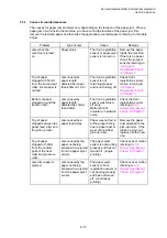
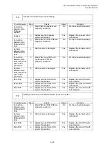
6. TROUBLESHOOTING OF THE CONTROL PANEL
L-1
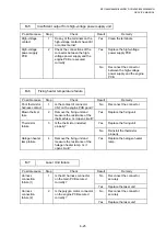
Nothing is displayed on the LCD.
User Check
(1) Verify if the power switch is turned off.
Possible cause
Step
Check
Result
Remedy
Connection
between main
PCB, relay PCB,
and control
panel PCB
1
Main PCB and control panel
PCB are properly connected.
No
Fix the connector properly.
Harness
between main
PCB, relay PCB,
and control
panel PCB
2
Harness wire is damaged.
Yes
Replace the harness with a
normal part.
Connection
between main
PCB and low-
voltage power
supply PCB
3
Main PCB and low-voltage
power supply PCB are
properly connected.
No
Fix the connection properly.
Harness
between main
PCB and low-
voltage power
supply PCB LCD
4
Harness wire is damaged.
Yes
Replace the harness with a
normal part.
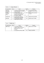
LCD 5
Replacement of LCD solves
the problem.
Yes
Replace the LCD with a
normal part.
Control panel
PCB
6
Replacement of control panel
PCB solves the problem.
Yes
Replace the control panel
PCB with a normal part.
Relay PCB
7
Replacement of relay PCB
solves the problem.
Yes
Replace the relay PCB with a
normal part.
Low-voltage
power supply
PCB
8
Replacement of low-voltage
power supply PCB solves the
problem.
Yes
Replace the low-voltage
power supply PCB with a
normal part.
Main PCB
9
Replacement of main PCB
solves the problem.
Yes
Replace the main PCB with
a normal part.
Содержание DCP-8040
Страница 146: ...CHAPTER 4 DISASSEMBLY AND RE ASSEMBLY 4 64 5 Remove the shutter arm C Fig 4 115 Shutter arm C Frame L ...
Страница 276: ...CHAPTER 7 MAINTENANCE MODE 7 6 Fig 7 3 l m a b c d e f g h i j k ...
Страница 347: ...APPENDIX 4 CIRCUIT DIAGRAMS A 50 Appendix 4 1 Main PCB Circuit Diagram 1 7 ...
Страница 348: ...MFC 8440 8840D 8840DN DCP 8040 8045D 8045DN SERVICE MANUAL A 51 Appendix 4 2 Main PCB Circuit Diagram 2 7 ...
Страница 349: ...APPENDIX 4 CIRCUIT DIAGRAMS A 52 Appendix 4 3 Main PCB Circuit Diagram 3 7 ...
Страница 350: ...MFC 8440 8840D 8840DN DCP 8040 8045D 8045DN SERVICE MANUAL A 53 Appendix 4 4 Main PCB Circuit Diagram 4 7 ...
Страница 351: ...APPENDIX 4 CIRCUIT DIAGRAMS A 54 Appendix 4 5 Main PCB Circuit Diagram 5 7 ...
Страница 352: ...MFC 8440 8840D 8840DN DCP 8040 8045D 8045DN SERVICE MANUAL A 55 Appendix 4 6 Main PCB Circuit Diagram 6 7 ...
Страница 353: ...APPENDIX 4 CIRCUIT DIAGRAMS A 56 Appendix 4 7 Main PCB Circuit Diagram 7 7 ...
Страница 354: ...MFC 8440 8840D 8840DN DCP 8040 8045D 8045DN SERVICE MANUAL A 57 Appendix 4 8 Driver PCB Circuit Diagram ...
Страница 355: ...APPENDIX 4 CIRCUIT DIAGRAMS A 58 Appendix 4 9 Engine PCB Circuit Diagram 1 2 ...
Страница 356: ...MFC 8440 8840D 8840DN DCP 8040 8045D 8045DN SERVICE MANUAL A 59 Appendix 4 10 Engine PCB Circuit Diagram 2 2 ...
Страница 357: ...APPENDIX 4 CIRCUIT DIAGRAMS A 60 Appendix 4 11 NCU PCB Circuit Diagram U S A ...
Страница 358: ...MFC 8440 8840D 8840DN DCP 8040 8045D 8045DN SERVICE MANUAL A 61 Appendix 4 12 NCU PCB Circuit Diagram Europe ...
Страница 359: ...APPENDIX 4 CIRCUIT DIAGRAMS A 62 Appendix 4 13 NCU PCB Circuit Diagram Asia ...
Страница 360: ...MFC 8440 8840D 8840DN DCP 8040 8045D 8045DN SERVICE MANUAL A 63 Appendix 4 14 NCU PCB Circuit Diagram Oceania ...
Страница 361: ...APPENDIX 4 CIRCUIT DIAGRAMS A 64 Appendix 4 15 Control Panel PCB Circuit Diagram ...
Страница 363: ...APPENDIX 4 CIRCUIT DIAGRAMS A 66 Appendix 4 17 Low voltage Power Supply PCB Circuit Diagram 100V ...
Страница 365: ...APPENDIX 4 CIRCUIT DIAGRAMS A 68 Appendix 4 19 High voltage Power Supply PCB Circuit Diagram 100V ...
Страница 367: ...April 04 SM FAX027 5 8C5903 Printed in Japan ...