


APPENDIX 3 FIRMWARE SWITCHS (WSW)
A-12
l
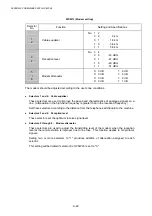
Selectors 5 and 6:
Busy tone detection in automatic sending mode
These selectors determine whether or not the machine automatically disconnects a line upon
detection of a busy tone in automatic sending mode.
Setting selector 6 to "0" ignores a busy tone so that the machine does not disconnect the line.
Setting selectors 5 and 6 to "0" and "1," respectively, makes the machine detect a busy tone
only after dialing and disconnect the line.
Setting both of selectors 5 and 6 to "1" makes the machine detect a busy tone before and
after dialing and then disconnect the line.
l
Selector 7: Busy tone detection in automatic receiving mode
This selector determines whether or not the machine automatically disconnects a line upon
detection of a busy tone in automatic receiving mode.
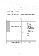
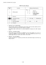
WSW06 (Pause button setting and 2nd dial tone detection)
Selector
No.
Function
Setting and Specifications
1
|
3
Pause
button setting and 2nd dial
tone detection
No. 1 2 3
0 0 0 :
No
pause
0 0 1 :
3.5 sec. WAIT
0 1 0 :
7 sec. WAIT
0 1 1 :
10.5 sec. WAIT
1 0 0 :
14 sec. WAIT
1 1 0 :
2nd dial tone detection
only in pulse dialing (DP)
system
1 0 1 :
2nd dial tone detection
1 1 1 :
both in DP and push-button
(PB)
dialing
system
4
|
6
Detection of 2nd dial tone
No. 4 5 6
0 0 0 :
50
ms
0 0 1 : 210
ms
0 1 0 : 500
ms
0 1 1 : 800
ms
1 0 0 : 900
ms
1 0 1 : 1.5
sec.
1 1 0 : 2.0
sec.
1 1 1 : 2.5
sec.
7
No. of 2nd dial tone detection times
0: Once
1: Twice
8
2nd dial tone interrupt detecting
time
0: 30 ms
1: 50 ms
Содержание DCP-8040
Страница 146: ...CHAPTER 4 DISASSEMBLY AND RE ASSEMBLY 4 64 5 Remove the shutter arm C Fig 4 115 Shutter arm C Frame L ...
Страница 276: ...CHAPTER 7 MAINTENANCE MODE 7 6 Fig 7 3 l m a b c d e f g h i j k ...
Страница 347: ...APPENDIX 4 CIRCUIT DIAGRAMS A 50 Appendix 4 1 Main PCB Circuit Diagram 1 7 ...
Страница 348: ...MFC 8440 8840D 8840DN DCP 8040 8045D 8045DN SERVICE MANUAL A 51 Appendix 4 2 Main PCB Circuit Diagram 2 7 ...
Страница 349: ...APPENDIX 4 CIRCUIT DIAGRAMS A 52 Appendix 4 3 Main PCB Circuit Diagram 3 7 ...
Страница 350: ...MFC 8440 8840D 8840DN DCP 8040 8045D 8045DN SERVICE MANUAL A 53 Appendix 4 4 Main PCB Circuit Diagram 4 7 ...
Страница 351: ...APPENDIX 4 CIRCUIT DIAGRAMS A 54 Appendix 4 5 Main PCB Circuit Diagram 5 7 ...
Страница 352: ...MFC 8440 8840D 8840DN DCP 8040 8045D 8045DN SERVICE MANUAL A 55 Appendix 4 6 Main PCB Circuit Diagram 6 7 ...
Страница 353: ...APPENDIX 4 CIRCUIT DIAGRAMS A 56 Appendix 4 7 Main PCB Circuit Diagram 7 7 ...
Страница 354: ...MFC 8440 8840D 8840DN DCP 8040 8045D 8045DN SERVICE MANUAL A 57 Appendix 4 8 Driver PCB Circuit Diagram ...
Страница 355: ...APPENDIX 4 CIRCUIT DIAGRAMS A 58 Appendix 4 9 Engine PCB Circuit Diagram 1 2 ...
Страница 356: ...MFC 8440 8840D 8840DN DCP 8040 8045D 8045DN SERVICE MANUAL A 59 Appendix 4 10 Engine PCB Circuit Diagram 2 2 ...
Страница 357: ...APPENDIX 4 CIRCUIT DIAGRAMS A 60 Appendix 4 11 NCU PCB Circuit Diagram U S A ...
Страница 358: ...MFC 8440 8840D 8840DN DCP 8040 8045D 8045DN SERVICE MANUAL A 61 Appendix 4 12 NCU PCB Circuit Diagram Europe ...
Страница 359: ...APPENDIX 4 CIRCUIT DIAGRAMS A 62 Appendix 4 13 NCU PCB Circuit Diagram Asia ...
Страница 360: ...MFC 8440 8840D 8840DN DCP 8040 8045D 8045DN SERVICE MANUAL A 63 Appendix 4 14 NCU PCB Circuit Diagram Oceania ...
Страница 361: ...APPENDIX 4 CIRCUIT DIAGRAMS A 64 Appendix 4 15 Control Panel PCB Circuit Diagram ...
Страница 363: ...APPENDIX 4 CIRCUIT DIAGRAMS A 66 Appendix 4 17 Low voltage Power Supply PCB Circuit Diagram 100V ...
Страница 365: ...APPENDIX 4 CIRCUIT DIAGRAMS A 68 Appendix 4 19 High voltage Power Supply PCB Circuit Diagram 100V ...
Страница 367: ...April 04 SM FAX027 5 8C5903 Printed in Japan ...