


MFC-8440/8840D/8840DN, DCP-8040/8045D/8045DN
SERVICE MANUAL
A-17
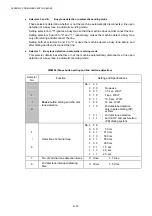
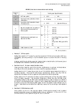
WSW10 (Protocol definition 2)
Selector
No.
Function
Setting and Specifications
1
Not used.
2
Time length from transmission of
the last dial digit to CML ON
0: 100 ms
1: 50 ms
3
Time length from CML ON to CNG
transmission
0: 2 sec.
1: 4 sec.
4
Time length from CML ON to CED
transmission (except for facsimile-
to-telephone switching)
0: 0.5 sec.
1: 2 sec.
5
6
No. of training retries
No. 5 6
0
0
:
1
time
0
1
:
2
times
1
0
:
3
times
1
1
:
4
times
7
Encoding system
MR 0:
Allowed 1:
Not
allowed
8
(Compression)
MMR
0:
Allowed 1:
Not
allowed
l
Selector 2: Time length from transmission of the last dial digit to CML ON
This selector sets the time length from when the machine transmits the last dial digit until the
CML relay comes on.
l
Selector 3: Time length from CML ON to CNG transmission
This selector sets the time length until the machine transmits a CNG after it turns on the CML
relay.
l
Selector 4: Time length from CML ON to CED transmission
This selector sets the time length until the machine transmits a CED after it turns on the CML
relay. This setting does not apply to switching between facsimile and telephone.
l
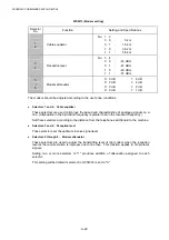
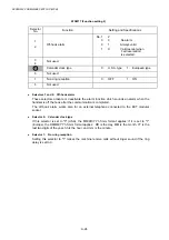
Selectors 5 and 6: No. of training retries
These selectors set the number of training retries to be repeated before automatic fallback.
l
Selectors 7 and 8: Encoding system (Compression)
This selector determines whether or not use of the MR/MMR coding system will be allowed.
Содержание DCP-8040
Страница 146: ...CHAPTER 4 DISASSEMBLY AND RE ASSEMBLY 4 64 5 Remove the shutter arm C Fig 4 115 Shutter arm C Frame L ...
Страница 276: ...CHAPTER 7 MAINTENANCE MODE 7 6 Fig 7 3 l m a b c d e f g h i j k ...
Страница 347: ...APPENDIX 4 CIRCUIT DIAGRAMS A 50 Appendix 4 1 Main PCB Circuit Diagram 1 7 ...
Страница 348: ...MFC 8440 8840D 8840DN DCP 8040 8045D 8045DN SERVICE MANUAL A 51 Appendix 4 2 Main PCB Circuit Diagram 2 7 ...
Страница 349: ...APPENDIX 4 CIRCUIT DIAGRAMS A 52 Appendix 4 3 Main PCB Circuit Diagram 3 7 ...
Страница 350: ...MFC 8440 8840D 8840DN DCP 8040 8045D 8045DN SERVICE MANUAL A 53 Appendix 4 4 Main PCB Circuit Diagram 4 7 ...
Страница 351: ...APPENDIX 4 CIRCUIT DIAGRAMS A 54 Appendix 4 5 Main PCB Circuit Diagram 5 7 ...
Страница 352: ...MFC 8440 8840D 8840DN DCP 8040 8045D 8045DN SERVICE MANUAL A 55 Appendix 4 6 Main PCB Circuit Diagram 6 7 ...
Страница 353: ...APPENDIX 4 CIRCUIT DIAGRAMS A 56 Appendix 4 7 Main PCB Circuit Diagram 7 7 ...
Страница 354: ...MFC 8440 8840D 8840DN DCP 8040 8045D 8045DN SERVICE MANUAL A 57 Appendix 4 8 Driver PCB Circuit Diagram ...
Страница 355: ...APPENDIX 4 CIRCUIT DIAGRAMS A 58 Appendix 4 9 Engine PCB Circuit Diagram 1 2 ...
Страница 356: ...MFC 8440 8840D 8840DN DCP 8040 8045D 8045DN SERVICE MANUAL A 59 Appendix 4 10 Engine PCB Circuit Diagram 2 2 ...
Страница 357: ...APPENDIX 4 CIRCUIT DIAGRAMS A 60 Appendix 4 11 NCU PCB Circuit Diagram U S A ...
Страница 358: ...MFC 8440 8840D 8840DN DCP 8040 8045D 8045DN SERVICE MANUAL A 61 Appendix 4 12 NCU PCB Circuit Diagram Europe ...
Страница 359: ...APPENDIX 4 CIRCUIT DIAGRAMS A 62 Appendix 4 13 NCU PCB Circuit Diagram Asia ...
Страница 360: ...MFC 8440 8840D 8840DN DCP 8040 8045D 8045DN SERVICE MANUAL A 63 Appendix 4 14 NCU PCB Circuit Diagram Oceania ...
Страница 361: ...APPENDIX 4 CIRCUIT DIAGRAMS A 64 Appendix 4 15 Control Panel PCB Circuit Diagram ...
Страница 363: ...APPENDIX 4 CIRCUIT DIAGRAMS A 66 Appendix 4 17 Low voltage Power Supply PCB Circuit Diagram 100V ...
Страница 365: ...APPENDIX 4 CIRCUIT DIAGRAMS A 68 Appendix 4 19 High voltage Power Supply PCB Circuit Diagram 100V ...
Страница 367: ...April 04 SM FAX027 5 8C5903 Printed in Japan ...