


MFC-8440/8840D/8840DN, DCP-8040/8045D/8045DN
SERVICE MANUAL
6-23
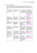
5. MALFUNCTIONS
When taking countermeasures for malfunctions as described in this section, check connectors
for contact failure before measuring the voltage at the specified connector pins.
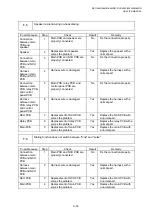
M-1
No AC power supplied
Possible cause
Step
Check
Result
Remedy
Supply voltage
1
Is the correct voltage present
at the outlet?
No
Inform the user that the
correct voltage is not supplied
at the outlet.
Power plug
2
Is the power cord securely
plugged into the outlet?
No
Plug the power cord securely
into the outlet.
Fuse (F1, F2)
3
Is the fuse blown?
Yes
If the fuse blows again
immediately after replacing
the low-voltage power supply
PCB, check that there is not a
short circuit somewhere in the
AC power supply line.
Wiring
4
Unplug the power supply plug.
Is there a broken wire between
the AC input connector of the
low-voltage power supply and
the power plug?
Yes
Replace the AC power cord.
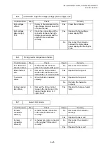
M-2
No DC power supplied
Possible cause
Step
Check
Result
Remedy
AC power
supply
1
Is AC power supplied between
connectors CN1-L and CN1-N
when the power plug is
plugged into the outlet?
No
Follow the same check
procedure of M-1 “No AC
power supplied”.
Wiring, DC load
2
Turn on the power switch.
Measure the voltages between
the terminals. Do the
measured voltage satisfy the
prescribed valued in the table
below?
Yes
Turn off the power switch,
reconnect the connector and
turn the power switch on
again. If the protector circuit
is activated, check the
connector, the wiring from the
connector, and the DC load.
Low-voltage
power supply
PCB
3
Refer to the chart *1 below.
No
Replace the low-voltage
power supply PCB.
*1
PCB
+lead pin
- lead pin
Voltage
Engine CN8-3
CN10-6
CN8-2
CN10-5
Approx. 24V
Approx. 3.3V
Содержание DCP-8040
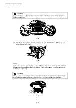
Страница 146: ...CHAPTER 4 DISASSEMBLY AND RE ASSEMBLY 4 64 5 Remove the shutter arm C Fig 4 115 Shutter arm C Frame L ...
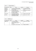
Страница 276: ...CHAPTER 7 MAINTENANCE MODE 7 6 Fig 7 3 l m a b c d e f g h i j k ...
Страница 347: ...APPENDIX 4 CIRCUIT DIAGRAMS A 50 Appendix 4 1 Main PCB Circuit Diagram 1 7 ...
Страница 348: ...MFC 8440 8840D 8840DN DCP 8040 8045D 8045DN SERVICE MANUAL A 51 Appendix 4 2 Main PCB Circuit Diagram 2 7 ...
Страница 349: ...APPENDIX 4 CIRCUIT DIAGRAMS A 52 Appendix 4 3 Main PCB Circuit Diagram 3 7 ...
Страница 350: ...MFC 8440 8840D 8840DN DCP 8040 8045D 8045DN SERVICE MANUAL A 53 Appendix 4 4 Main PCB Circuit Diagram 4 7 ...
Страница 351: ...APPENDIX 4 CIRCUIT DIAGRAMS A 54 Appendix 4 5 Main PCB Circuit Diagram 5 7 ...
Страница 352: ...MFC 8440 8840D 8840DN DCP 8040 8045D 8045DN SERVICE MANUAL A 55 Appendix 4 6 Main PCB Circuit Diagram 6 7 ...
Страница 353: ...APPENDIX 4 CIRCUIT DIAGRAMS A 56 Appendix 4 7 Main PCB Circuit Diagram 7 7 ...
Страница 354: ...MFC 8440 8840D 8840DN DCP 8040 8045D 8045DN SERVICE MANUAL A 57 Appendix 4 8 Driver PCB Circuit Diagram ...
Страница 355: ...APPENDIX 4 CIRCUIT DIAGRAMS A 58 Appendix 4 9 Engine PCB Circuit Diagram 1 2 ...
Страница 356: ...MFC 8440 8840D 8840DN DCP 8040 8045D 8045DN SERVICE MANUAL A 59 Appendix 4 10 Engine PCB Circuit Diagram 2 2 ...
Страница 357: ...APPENDIX 4 CIRCUIT DIAGRAMS A 60 Appendix 4 11 NCU PCB Circuit Diagram U S A ...
Страница 358: ...MFC 8440 8840D 8840DN DCP 8040 8045D 8045DN SERVICE MANUAL A 61 Appendix 4 12 NCU PCB Circuit Diagram Europe ...
Страница 359: ...APPENDIX 4 CIRCUIT DIAGRAMS A 62 Appendix 4 13 NCU PCB Circuit Diagram Asia ...
Страница 360: ...MFC 8440 8840D 8840DN DCP 8040 8045D 8045DN SERVICE MANUAL A 63 Appendix 4 14 NCU PCB Circuit Diagram Oceania ...
Страница 361: ...APPENDIX 4 CIRCUIT DIAGRAMS A 64 Appendix 4 15 Control Panel PCB Circuit Diagram ...
Страница 363: ...APPENDIX 4 CIRCUIT DIAGRAMS A 66 Appendix 4 17 Low voltage Power Supply PCB Circuit Diagram 100V ...
Страница 365: ...APPENDIX 4 CIRCUIT DIAGRAMS A 68 Appendix 4 19 High voltage Power Supply PCB Circuit Diagram 100V ...
Страница 367: ...April 04 SM FAX027 5 8C5903 Printed in Japan ...