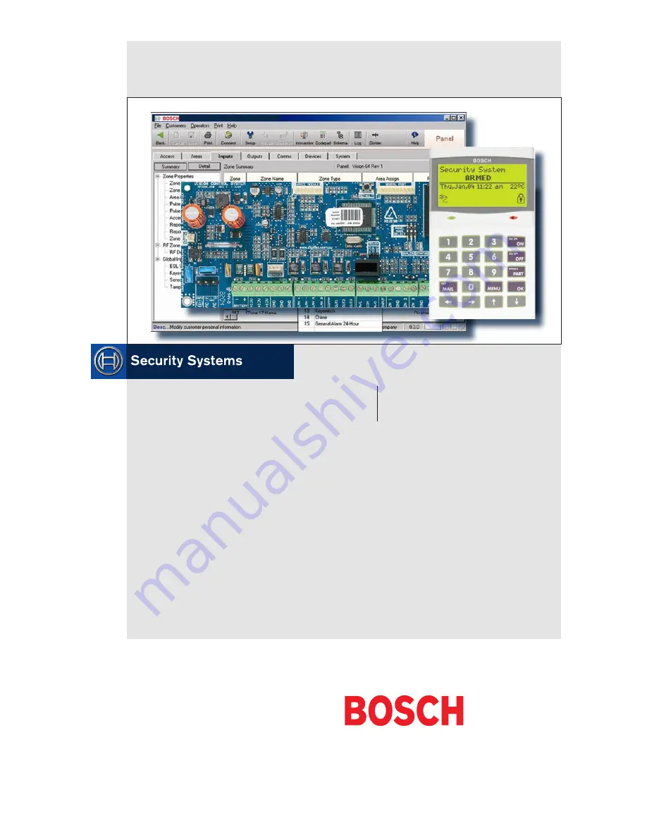
Solution 64
Installer Guide
EN Intrusion Control Panel
Страница 1: ...Solution 64 Installer Guide EN Intrusion Control Panel ...
Страница 2: ...y Ltd nor any of its official representatives shall have any liability to any person or entity with respect to any liability loss or damage caused or alleged to be caused directly or indirectly by the information contained in this book Bosch Security Systems Pty Ltd reserves the right to make changes to features and specifications at any time without prior notification in the interest of ongoing p...
Страница 3: ...e Table 4 5 Section 5 Access Programming 5 1 User Default Table 5 2 User PIN Codes 5 2 User Tokens 5 3 User RF Keyfobs 5 4 User Properties 5 5 Understanding Timer Groups 5 6 PROX READERS 5 8 Section 6 Area Programming 6 1 AREA COMMANDS 6 1 AREA PROPERTIES 6 2 Area Reporting 6 5 AREA TESTING 6 6 Section 7 Input Programming 7 1 Input Commands 7 1 Zone Default Table 7 3 ZONE PROPERTIES 7 4 Understand...
Страница 4: ...Solution 64 Installer Guide Contents iv Bosch Security Systems 11 05 BLCC110I Section 12 Programming Examples 12 1 Section 13 Specifications 13 1 Section 14 Index 14 1 ...
Страница 5: ... Built In Remote and Auto Arming Overview Zones The Solution 64 control panel provides up to 64 separate zones of protection Zone programming determines the panel s response to open short and tamper conditions on the zone loop Areas The control panel supports up to 8 separate areas You can assign all zones to a single area or you can assign each zone to a combination of different areas You can arm...
Страница 6: ...Solution 64 Installer Guide Section 1 Overview 1 2 Bosch Security Systems 11 05 BLCC110I This page left intentionally blank ...
Страница 7: ...ution Control Panel 2 Adjacent Module Spaces CM100 Voice Command Module 1 Module Space CM110 Output Expander 1 Module Space CM120 LAN Power Supply 1 Module Space CM130 RS232 Port Expander 1 Module Space CM140 GSM Modem Interface 1 Module Space CM150 TCP IP Interface 1 Module Space Using the above table the installer can determine how many modules can be mounted in a single enclosure On some export...
Страница 8: ...rtitioned press and hold the OFF key for two seconds The OK key allows you to save any changes and exit the command Key Description The MAIL key allows you to read stored mail This key can also be used to initiate a dialler test when you press and hold for two seconds The key allows you to move the cursor to the left when programming text or telephone numbers The key allows you to move the cursor ...
Страница 9: ... to turn on Red Green LED Flashing Installer programming mode is active Table 5 ICON LED Indicator Meanings Keypad Tones Your keypad emits several distinct tones and displays text to alert you to system events The volume of the keypad tones can be adjusted in MENU 6 1 0 Type Meaning Fire Alarm Tone When a fire zone sounds an alarm the keypad will sound 3 seconds on and 2 seconds off repeat Burglar...
Страница 10: ...2 4 Bosch Security Systems 11 05 BLCC110I Solution 64 Installer Guide Section 2 Installing the Hardware This page left intentionally blank ...
Страница 11: ... These diagrams show the zone wiring configurations using Normally Closed Alarm contacts and Normally Open Alarm Contacts When using Normally Open Alarm Contacts you must select Inverted Seal for each zone in MENU 3 1 8 A shorted loop is a tamper condition for all EOL zone configurations 2 ZONE 2 N O N O ZONE 1 Figure 7 N O No EOL Zone ZONE 2 ZONE 1 N O N O ALARM ALARM Figure 8 N O Single EOL Zone...
Страница 12: ...n of the A C plug pack transformer 4 5 BAT BAT Negative and positive connections to the stand by battery 12 VDC 7AH 6 7 8 9 10 11 12 V 12 V 12 V GND GND GND These terminals are used to power detectors and LAN devices up to 750 mA 12 13 LAN LAN These terminals are used to power LAN devices up to 750 mA 14 LAN A Connect the LAN A data terminal of any LAN device eg Keypads expansion boards to this te...
Страница 13: ...Solution 64 Installer Guide Wiring Diagrams Bosch Security Systems 11 05 BLCC110I 3 3 Figure 12 Terminal Descriptions ...
Страница 14: ...4 ZONE 1 ZONE 3 N C N C N C N C N C ZONE 6 ZONE 8 ZONE 5 ZONE 7 N C N C N C N C LAN B LAN LAN A LAN Keypad LAN Expansion Device HORN SPEAKER STROBE 12 VDC PIEZO NOTE Short Relay Select PINS COM and 12V 12VDC 7Ah Sealed Lead Acid Battery Accessories e g PIR Detectors Siren Tamper Switch Connect To Cabinet Tamper Connect To Zone Terminals NC COM RJ12 6P4C To RJ12 6P4C Telephone Lead Connect To Telep...
Страница 15: ...rea On Use the up and down arrow keys to navigate and press OK to select the command Programming Option Bit Menus Use the up and down arrow keys to scroll through the 8 different options To enable an option press the ON key a tick will be displayed To disable an option press the OFF key Off On Low Battery Show Overload Report Overload Press OK ON OFF MENU To save programming changes press OK or pr...
Страница 16: ...ble by scrolling using the up and down arrow keys Clock Programming Use the left and right arrow keys to move to the field and use the up and down keys to change Press OK to save or MENU to exit without saving i Note Scroll through the hours to change from am to pm SET DATE AND TIME i01 Jan 2005 12 00 am PreSS OK or MENU Telephone Numbers To program select primary telephone number under MENU 5 1 1...
Страница 17: ...ulting using MENU 7 7 4 If factory defaulting has been disabled you must know the installer PIN to perform a factory default otherwise the system will need to be returned to your supplier for defaulting Charges will apply 1 2 3 4 1 2 3 4 1 2 3 1 2 3 Triggering a Duress Alarm If your PIN is 2580 to send a duress report when the area is off Enter 2 5 8 0 8 0 OK or ON If your PIN is 2580 to send a du...
Страница 18: ...he horn speaker for two seconds Internal Audible Test Use MENU 4 9 1 to test and verify that all 12 VDC sirens operate This test will sound the siren for two seconds Strobe Test Use MENU 4 9 2 To test and verify that the strobe operates This test will turn on the strobe until you manually stop the test Battery Test Use MENU 7 9 1 to test the back up battery that is connected to the control panel C...
Страница 19: ...N M 1 1 1 Change Other PIN UMI 2 0 4 Move To Area AUMI 3 0 0 Zone Status MI 1 1 2 Add PIN AUMI 2 0 5 Chime On Off AUMI 4 0 0 Output Status MI 1 1 3 Delete PIN UMI 4 0 1 Turn Output On Off I 1 1 4 View PIN 2 1 Area Properties MI 7 1 0 Set Date Time MI 2 1 0 Area Name UMI 3 0 5 Smoke Sensor Reset 1 2 Token I 2 1 1 General Options UMI 3 9 0 Walk Test All Zones MI 1 2 0 Add Token I 2 1 2 Input Options...
Страница 20: ...rt Route MI 4 9 1 Internal Siren Test MI 5 1 5 Domestic Numbers I 3 1 7 Report Options MI 4 9 2 Strobe Test MI 5 1 6 Call Forward On I 3 1 8 Zone Options MI 5 1 7 Call Forward Off 3 3 RF Zone 5 2 Properties I 3 3 0 Add RF Device I 5 2 0 Call Attempt Count I 3 3 1 Delete RF Device I 5 2 1 Dialler Options I 3 3 2 Test RF Device I 5 2 2 Phone Line Options I 5 2 3 Country 3 4 Global Input Options I 5 ...
Страница 21: ...cy Keys I 7 2 3 Part Entry Time I 6 1 7 Access Group I 7 2 4 Auto Arm Pre Alert I 6 1 8 Lockout Time I 7 2 5 Output Pre Alert I 7 2 6 Senior Watch Time 6 2 RF Devices I 6 2 0 Receiver Options 7 3 Power I 6 2 1 SuperSolution Time I 7 3 0 AC Options I 6 2 2 RF Device Options I 7 3 1 Battery Options I 6 2 3 Add RF Keypad I 7 3 2 Fuse Options I 6 2 4 Delete RF Keypad I 6 2 5 View RF I D 7 4 Siren I 7 ...
Страница 22: ...Solution 64 Installer Guide Programming Overview 4 8 Bosch Security Systems 11 05 BLCC110I This page left intentionally blank ...
Страница 23: ...Group Index 5 Assign each restricted user to Timer Group 5 Schedules Schedules determine the valid operating times and days and then the schedule is linked to a timer group number Users which are to be restricted are then assigned to the same timer group number as the schedule Access Group A user can be restricted to certain doors within a building and this is done by assigning the user to one or ...
Страница 24: ...as the old PIN unless the variable code length option has been enabled See MENU 1 5 0 PIN Length Enter MENU 1 1 0 The keypad will prompt you to enter a new PIN Enter New PIN for Debbie Smith Ur002 Press OK or MENU Enter the new PIN then press OK If the error message PIN Not Allowed is displayed press OK and try a different PIN The keypad will now prompt you to confirm the new PIN again Confirm New...
Страница 25: ... 3 and use the up and down arrows to highlight the user in the list then press OK The system will only list users that can be deleted Ur001 John Smith Ur002 Debbie Smith Ur003 User 3 Name Press OK or MENU Press OK to delete the PIN or press MENU to cancel Press OK to delete PIN User Ur002 Debbie Smith Press OK or MENU 1 2 3 1 2 Access PIN Codes View PIN MENU 1 1 4 This menu allows the Installer to...
Страница 26: ...RF Keyfobs This section outlines how to add and delete RF keyfobs RF Keyfobs provide an alternate method for users to turn the system on and off There are two methods for adding RF Keyfobs Direct Entry and Learn Mode The system will prompt for the appropriate method depending on the Receiver type fitted to the system The RF Keyfob must be compatible with the RF Receiver that has been programmed in...
Страница 27: ...t 2 1 2 1 2 3 4 User Properties This section outlines user properties including User Name Area Assignment User Options Erase User and Access Group Access User Properties User Name MENU 1 4 0 U s e r 1 N a m e This menu allows the security Installer or a Master user to program the user s name max of 16 characters This name is used for System Greetings Reporting and Log entries to identify the user ...
Страница 28: ...to to turn the area on even though one or more zones are still faulted or open Upon arming the system 2 3 1 2 3 will prompt the user to automatically bypass each faulted zone To prevent users from being able to force arm an area you will need to disable this option Send Open Close Reports Setting this option will cause the system to send opening and closing reports when the user arms and disarms a...
Страница 29: ...gths For example User 1 could have a 4 digit code while user 3 can have an 8 digit code 2 3 1 2 3 Variable pin lengths are useful for increasing security levels Another use would be to program a single digit code to trigger an output To do this create a code which is not assigned to an area and then map this to the required output Enter MENU 1 5 0 The keypad will display the current PIN length PIN...
Страница 30: ...his menu programs which area 1 to 8 the Reader will operate Each external reader can only be assigned to operate a single area When using a prox keypad reader if you set the area assignment to a specific area number then only that area will arm disarm when a valid token is used If you set the area assignment to 0 zero and a token is presented then the keypad will move to the first area which that ...
Страница 31: ... have access to the Area that the Reader has been assigned to See MENU 1 6 1 Reader Area Assignment Badging Required Selecting this option allows the user to unlock a door and arm an Area from a single reader This option is only relevant if Arming Allowed has been selected When the area is disarmed presenting the Token once will unlock the door Presenting the Token 3 times within 5 seconds will ar...
Страница 32: ...Solution 64 Installer Guide Access Programming 5 10 Bosch Security Systems 11 05 BLCC110I This page left intentionally blank ...
Страница 33: ...e display This is selectable per keypad under MENU 6 1 4 General Options Once you log onto a keypad using your pin code OK the system knows who you are and will allow you to use the left arrow key to move from the current area to the next area that your assigned to To move areas without having to enter your code select the option under MENU 7 7 1 Area Options and then simply step through all the a...
Страница 34: ...ew If you move to another area the keypad will automatically revert back to its assigned home area after 2 minutes See Menu 6 1 3 Home Area Enter MENU 2 0 4 and select the area from the list and press OK to move to the selected area 1 2 1 2 1 A001 Security System A002 Area 2 Name A003 Area 3 Name Press OK or MENU i Note Turn off option Menu 6 1 4 Pin To change Area and use the and keys to move thr...
Страница 35: ...y cleared If this option is not programmed any trouble condition that occurs will not have to be acknowledged if it has already been rectified or cleared 1 2 3 Single Button Arming Allowed All On This option allows users to simply press the ON key to turn the area ON All zones being armed must be sealled If open and close reports are programmed the user ID number will report as 000 Single Button A...
Страница 36: ...xit without saving Arm Disarm Speaker Beeps Via RF Key Fob This option allows audible beeps via the speaker output to verify to the user that they have successfully turned the area On or Off using the RF keyfob The speaker output will sound One beep for Off two beeps for On and three beeps for Part On 1 2 3 Arm Disarm Speaker Beeps Via Keyswitch This option allows audible beeps via the speaker out...
Страница 37: ... or press MENU to exit without saving Audible Burglary Alarm When selected the panel will activate the strobe output when an audible burglary zone has triggered an alarm 1 2 3 Silent Burglary Alarm When selected the panel will activate the strobe output when a silent burglary zone has triggered an alarm Fire Alarm When selected the panel will activate the strobe output when a zone programmed as fi...
Страница 38: ...nter the number of weeks that an area can remain turned off betore a trouble condition will occur Valid entries are 1 255 Weeks or 000 to disable Press OK to save and exit or press MENU to exit without saving 2 3 1 2 3 1 2 3 Areas Area Testing User Test Interval MENU 2 9 1 0 0 0 System Wide Parameter DAYS This menu sets the number of days before it will prompt the user to walk test the system To c...
Страница 39: ...NU Repeat Step 2 until all options are programmed as required then press OK to save and exit or press MENU to exit without saving User Test Required This option allows the keypad assigned to the corresponding area to display a trouble condition when a user test is due The trouble condition can be cleared by performing a walk test Walk Test Reports This option allows the corresponding area to send ...
Страница 40: ...Solution 64 Installer Guide Area Programming 6 8 Bosch Security Systems 11 05 BLCC110I This page left intentionally blank ...
Страница 41: ...for zones you don t want to be able to bypass for example 24hr fire holdup or panic zone types The PGM input is a special input that can be configured to accept data from a number of different RF receiver manufacturers or simply be used as an keyswitch input The tamper options configure the system behaviour for enclosure tamper alarms and also for the enclosure tamper of the peripheral devices Inp...
Страница 42: ...ass Press ON Press OK or MENU Press ON or OFF to toggle the zone s bypass state then Press OK to save and exit or press MENU to exit without saving Repeat steps 1 to 4 to bypass or un bypass additional zones 3 4 5 1 2 3 4 5 Inputs Commands Set Chime Zones MENU 3 0 3 This menu allows you to program zones to be monitored when chime mode is activated Chime mode is ideal for monitoring a front door in...
Страница 43: ...ort Route 2 2 2 2 2 2 Reporting Options Lockout Dialler Y Y Y Y Y Y Report Alarm Y Y Y Y Y Y Report Alarm Restore Y Y Y Y Y Y Report Trouble Y Y Y Y Y Y Report Trouble Restore Y Y Y Y Y Y Report Bypass Y Y Y Y Y Y Report Bypass Restore Y Y Y Y Y Y Delay Report N N N N N N Zone Options Lockout Siren Y Y Y Y Y Y Silent Alarm N N N N N N Inverted Seal N N N N N N Bypass Allowed Y Y Y Y Y Y Sensor Wat...
Страница 44: ...configure the zone type or behaviour for every zone in the system Each zone should be assigned to a Zone Type that defines the way in which the panel will respond when an alarm is triggered on that zone Refer to the table and descriptions below for the available Zone Type selections Zone Types 0 Zone Not Used 1 Burglary Delay 1 Entry Timer 1 2 Burglary Delay 2 Entry Timer 2 3 Burglary Instant 1 Wi...
Страница 45: ...ency including the presence of one or more unwanted persons trying to gain entry to the premises It will sound an alarm at any time as soon as the zone becomes faulted regardless of what state the area is in A 24hr Panic report will be sent to the central station receiver 11 Fire 24 Hour This zone type is used for Fire and Smoke detector alarms Zones programmed as 24hr Fire will trigger an alarm a...
Страница 46: ... door access group you need to select an unused Access Group number from 1 to 8 in this example we will assume the Access Group number to be 5 Under user properties assign the users who you wish to have access to Access Group 5 Remember that you are able to assign users to more than one Access Group Now select the output that will be used to operate the door strike and assign it to Access Group 5 ...
Страница 47: ...or the respective zone s All zones in the system can be individually programmed for Dialler Lockout When enabled the zone will be allowed to transmit alarm reports each time it is triggered provided that the Swinger Dialler count has not been reached If the zone is triggered and the Swinger Dialler count has been reached then the zone will become locked out and no further reports will be sent for ...
Страница 48: ...n allows a normally open sensor or device to operate as a normally closed device by reversing the open closed state of the zone loop eg When the zone loop is open the system will register the zone loop as closed or normal Bypass Allowed Setting this option allows users with the appropriate access level to manually bypass this zone effectively removing it from the area for the current arming cycle ...
Страница 49: ...ress OK ON OFF MENU OK to delete RF zone for Zn001 Zone 1 Name 007407097 Press OK or MENU 1 2 3 1 Press OK to DELETE the RF device and exit or press MENU to exit without deleting RF Sensor Learn Mode Press MENU 3 3 0 and use the up and down arrows to highlight the zone you want to program in the list and press OK Alternatively you can enter the zone number directly and press OK The system will onl...
Страница 50: ...in the report Press MENU 3 4 1 The keypad will display the current keyswitch options Default 0 Disabled Keyswitch Options 00 Latching All On Off Press 0 9 OK to Save 1 2 1 Use the up and down arrows to select the required keyswitch option then press OK to save and exit or press MENU to exit without saving Inputs Global Input Options Input Options MENU 3 4 2 1 Tamper On Short N 2 Reserved N 3 Respo...
Страница 51: ... Expander Tamper Setting this option enables peripheral tamper reporting Audible Expander Tamper Setting this option causes the system to trigger an audible alarm when a peripheral tamper is triggered 1 2 3 Input Testing Inputs Input Testing Walk Test All Zones MENU 3 9 0 This menu allows you to test all zones within an area at the same time To perform a successfull walk test each zone in the area...
Страница 52: ...al and unseal at least once within the Sensor Watch Time period or a trouble message will be displayed on the keypad and a Zone Trouble report sent Valid entries are 1 255 Days and 0 Sensor Watch Disabled Press MENU 3 9 2 The keypad will display the current sensor watch time Default 30 days SensorWatch Time 030 Days Press 0 9 OK or MENU Using the numeric keys enter the new Sensor Watch time in day...
Страница 53: ...u to switch positive or negative without the need to add additional wiring The outputs are all protected and will shut down individually under overload conditions A report will be generated and a displayed on the keypad to indicate the trouble condition Output Commands Outputs Commands Output Status MENU 4 0 0 This command allows you to view the current status of any system output Press MENU 4 0 0...
Страница 54: ...anual test can also be requested at any time while the system is disarmed See MENU 7 9 1 Battery Test 2 AC Trouble This event type will cause the output to operate when the panel detects that the AC mains power has been missing for 1 minute and will reset when the power has been restored for 1 minute 3 Telephone Line Trouble This event type will cause the output to operate when the panel detects t...
Страница 55: ...Area Disarmed This event type will cause the output to operate as soon as the corresponding area is disarmed and will reset when the area is armed in either the All On or Part On modes If the output event assignment for this output is set to zero all areas then all areas must be disarmed for the output to operate The output will reset as soon as any area is armed in either the All On or Part On mo...
Страница 56: ...pe will cause the output to operate when any audible alarm occurs The output will reset when the system or area is disarmed This event type will also generate speaker beeps when the system or area is armed via a RF Keyfob the Programmable Input Terminal or Keyswitch zone 1 beep when the area is disarmed 2 beeps when the area is armed All On 3 beeps when the area is armed Part On 37 Internal Siren ...
Страница 57: ...ssed on the Keyfob This function requires a 4 button keyfob 55 Output Pre Alert This event type will cause the output to operate when the output pre alert timer is active and will reset when the pre alert timer expires 56 Follow PIN This event type will cause the output to operate when a specified user PIN is entered via the keypad or when the corresponding user s keyfob or token is used You shoul...
Страница 58: ... The output will run for the full duration and cannot be manually reset Normally Open One Show Low Retrigger Output is normally open circuit and switches to GND when the event occurs The output will retrigger each time the event occurs The output will reset when the one shot time has expired This polarity is ideally suited for security lighting control A sensor can be used to trigger an output eve...
Страница 59: ...reset 1 2 3 Outputs Properties Output Options MENU 4 1 5 1 Do Not Operate On Low Battery Y 2 Display Overload Y 3 Report Overload Y 4 Display Device Fail Y 5 Report Device Fail Y 6 Alarm On Device Fail N 7 Reserved N 8 Display Status Message N Press MENU 4 1 5 and select the output you want to program from the list then press OK Alternatively you can directly enter the output number then press OK ...
Страница 60: ...med as event type 37 Internal Audible or event type 39 Fire Alarm for 5 seconds Enter MENU 4 9 1 and select the area you want to test the internal sirens in from the list then press OK Any outputs programmed for event type 37 or 39 in the chosen area will now operate The keypad will display the following during the siren test Internal Audible Testing Press any key to Abort Press OK or MENU When th...
Страница 61: ...ea Disarmed A 46 Device Tamper A S Schedule Event Assignment 22 Area Armed Any A 47 Access Denied A G Access Group Event Assignment 23 Area All On A 48 Strobe A K Keypad 24 Area Part On A 49 Smoke Sensor GND A 25 Area Part 2 On A 50 Sensor Watch A Table19 Output Event Types Output Default Table The table below lists the default values for all Output parameters in the Solution 64 Outputs 1 to 3 are...
Страница 62: ...Solution 64 Installer Guide Output Programming 8 10 Bosch Security Systems 11 05 BLCC110I This page left intentionally blank ...
Страница 63: ...so the system will always send the same reporting code for the same event The type of zone selected under zone type automatically determines the reporting code to the base station If a zone is defined as Medical then when it goes into alarm the report will be Medical Alarm if a zone is programmed as a Fire zone then the report will automatically be Fire Alarm Comms Programming Commands Comms Comma...
Страница 64: ...is ON To Turn OFF Press OFF To Go Back Press OK To toggle call forward on press the ON key or press the OFF key to turn call forward off Press OK to save and exit or press MENU to cancel 5 7 1 2 3 4 i Note See MENU 5 1 6 and MENU 5 1 7 to program the Call Forward ON and Call Forward OFF number sequence Comms Commands Check Web Email MENU 5 0 3 Reserved Comms Commands Email System Log MENU 5 0 4 Re...
Страница 65: ...be required when the panel is configured for dual reporting Enter MENU 5 1 3 The keypad will display the current Primary Telephone Number for Destination 2 Primary Dest 2 P001 Press 0 9 OK to SAVE Using the numeric keys enter all the digits of the telephone number You can change a single digit by scrolling the cursor left or right For special characters including pause or use the up and down arrow...
Страница 66: ...line and dial the number sequence and then hang up In Australia a typical sequence for deactivating the Call Forward On feature All Calls might be 61 61 diversion type Call Forward On Immediate end of sequence 1 2 3 Enter MENU 5 1 7 The keypad will display any current Call Forward Off sequences Call Forward Off N001 Press 0 9 OK to SAVE Using the numeric keys enter all digits for the sequence You ...
Страница 67: ...option sets the panel to wait for up to 60 seconds to receive a valid handshake signal from the base station receiver The handshake tone indicates to the panel that it has reached the security company s base station receiver and can now send it s pending reports If this option is disabled the handshake wait time will default to 30 seconds Abort Failled Reports Setting this option will cause a fail...
Страница 68: ...that the correct country selection is made for your location If your country is not listed here please contact your Bosch distibutor 1 2 4 Comms Properties Set SMS Password MENU 5 2 7 p a s s w d This menu sets the SMS password which is required whenever SMS reporting is selected The password will typically be defined by the service provider or Telco carrier who you are using to route the message ...
Страница 69: ...he Log Threshold option is programmed the panel will send a Log Threshold report to the base station when the event log reaches the percentage as set since the last SolutionLink session 1 2 3 1 2 3 If the event log reaches 100 capacity before a SolutionLink RAS session is established then the system will send a Log Overflow report The panel will also log these events in its memory Press MENU 5 3 2...
Страница 70: ...ective Remote Program Editing Only When Disarmed Setting this option will prevent a SolutionLink RAS connection to the panel while any are is armed 2 3 1 2 1 2 Allow User Functions Via Remote Access Software Setting this option allows access to user functions via the RAS upload download software If this option is not programmed user functions will be disabled Report RAS Start End Sessions Setting ...
Страница 71: ...rmation for CLI number 1 CLI Number 1 Press 0 9 OK to SAVE 1 2 1 Using the numeric keys enter all the digits for CLI number 1 You can change a single digit by scrolling the cursor left or right For special characters including pause or use the up and down arrow keys Press OK to program CLI number 2 CLI Number 2 Press 0 9 OK to SAVE Using the numeric keys enter all the digits for CLI number 2 Press...
Страница 72: ... Press MENU 5 4 2 The keypad will display the current Test Route Test Route 01 Dest 1 Log Press 0 9 OK to SAVE Use the up and down arrow keys to select the Test Route required then Press OK to save and exit or press MENU to exit without saving 1 2 1 2 Comms Dialler Reporting Status Route MENU 5 4 3 0 Report Events To Log Only 1 1 Report Events To Destination 1 Log 2 Report Events To Destination 2 ...
Страница 73: ...e Press MENU 5 4 6 The keypad will display the current burglary report delay time Burg Report Delay 000 seconds Press 0 9 OK to SAVE Using the numeric keys enter the new report delay time then press OK to save and exit or press MENU to exit without saving Valid entires are 0 to 255 seconds 1 2 1 2 Comms Dialler Reporting Fire Report Delay MENU 5 4 7 0 0 0 System Wide Parameter SECONDS This menu pr...
Страница 74: ...iod 3 4 1 2 1 Test Report Period 01 Every Day Press 0 9 OK to SAVE Use the up and down arrow keys to select the Test Report Period then Press OK to save and exit or press MENU to exit without saving Comms Comms Test Test Report Options MENU 5 9 3 1 Send Test Reports Only If No Other Report N 2 Send Test Reports On Audible Time Out Y 3 Reserved N 4 Reserved N 5 Reserved N 6 Reserved N 7 Reserved N ...
Страница 75: ...rovides a quick and easy way for the Installer to test the communication path for the panel while they are onsite without the need to trigger test reports and then verify them with the base station Once the telco wiring has been completed enter your mobile phone or another test number into this location and press OK The panel will then seize the phone line and dial the programmed number Press MENU...
Страница 76: ...Solution 64 Installer Guide Comms Programming 9 14 Bosch Security Systems 11 05 BLCC110I This page left intentionally blank ...
Страница 77: ...o highlight the keypad in the list and press OK The display will show the keypad status Kp001 Keypad 001 Kp002 Keypad 002 Press OK or MENU The status line will scroll the keypad voltage temperature and home area while the keypad type and firmward version number are continuously displayed Keypad 001 K001 Graphic Prox v001 Volts 13 87 Press OK or MENU Press OK or MENU to exit when finished 1 2 3 Dev...
Страница 78: ...number directly and press OK 2 3 3 1 L Keypad 001 Volume Press SAVE OK to H Use the arrow keys to set the required volume level Each time a key is pressed you will hear a beep indicating the new volume level When finished press OK i Note To completely silence the keypad speaker simply move the slider all the way to the left This will disable the keypad speaker for all functions including key press...
Страница 79: ...nfigures the panel to automatically turn off the keypad backlighting after an inactivity period of 60 seconds As soon as a key is pressed or an alarm occurs the keypad backlight will turn on Greeting On Arm Setting this option configures the keypad to display a farewell greeting when the user arms an area The greeting will include the user name if programmed Greeting On Disarm Setting this option ...
Страница 80: ...le to trigger a temperature alarm based on the keypad temperature See MENU 7 7 3 Keypad Hi Lo Temp for more information 1 2 3 Devices Keypads Emergency Keys MENU 6 1 6 1 Audible Keypad Fire Y 2 Report Keypad Fire Y 3 Audible Keypad Medical Y 4 Report Keypad Medical Y 5 Audible Keypad Panic Invisible If Not Set N 6 Report Keypad Panic N 7 Reserved N 8 Reserved N The above options can be configured ...
Страница 81: ...his option allows the panel to display a trouble condition on the keypad when an RF receiver fail condition occurs Alarm On RF Receiver Tamper Setting this option allows the panel to trigger an alarm when the RF receiver tamper circuit is tripped Report Faulted RF Receiver Tamper Setting this option allows the panel to send an RF Receiver Tamper report to the the base station when the RF receiver ...
Страница 82: ...panel to send a report to the base station when the RF device signals to the panel that it has a low battery condition Unseal Zone On RF Device Missing Setting this option will cause the panel to show a zone fault on the keypad for any RF devices that are missing Report RF Device Missing Setting this option will cause the panel to send a report to the base station if the panel detects that an RF d...
Страница 83: ...o exit without saving Devices Serial Device Flow Control MENU 6 3 2 0 No Handshaking 0 1 Hardware 2 Xon Xoff This menu sets the appropriate flow control for the device you are connecting the serial board to The flow control method must be the same on both devices for a serial connection to be established Press MENU 6 3 2 The keypad will display the current flow control setting 1 2 1 2 1 Flow Contr...
Страница 84: ... 2 Reserved Reserved for future use Devices Access Controller Options MENU 6 7 2 1 Reserved N 2 Reserved N 3 Reserved N 4 Reserved N 5 Reserved N 6 Reserved N 7 Reserved N 8 Reserved N Reserved for future use Devices Access Controller Options MENU 6 7 3 1 Reserved N 2 Reserved N 3 Reserved N 4 Reserved N 5 Reserved N 6 Reserved N 7 Reserved N 8 Reserved N Reserved for future use Devices X10 Device...
Страница 85: ...tem troubles which are currently in effect on the system Information is diplayed in a list format allowing you to select a paticular event and then drill down to view more specific information System trouble events such as Failure To Comminicate or Telco Line Fail are grouped under System Trouble in the list while 1 3 open zones are displayed individually one per line When the keypad is in standby...
Страница 86: ... system device which is connected to the LAN bus e g keypad etc Default PIN Trbl This trouble message will display if the panel detects that either the Installer PIN or User 1 PIN is still set to the factory default PIN Change the PIN to clear the fault Date And Time This trouble message will display if the system date and time has not been set Program the correct date and time to clear the fault ...
Страница 87: ...ame Walk Test Exited A1 Press OK or MENU Use the up and down arrows keys to scroll between history events When finished press OK or MENU to exit 1 2 3 System Commands Domestic Default MENU 7 0 3 This command will configure the control panel for Domestic format reporting eg mobile telephones etc All alarm restore reports and open close reporting options will be automatically disabled Therefore only...
Страница 88: ...1 2 When the time is set correctly press OK to save and exit or press MENU to exit without saving System Clock Summertime On MENU 7 1 1 At 2 00am Month Week Day This menu allows you to program when day light savings start during the year This will allow the panel to automatically adjust it s built in clock accordingly In Australia daylight savings moves forward one hour at 2 00 am on the last Sund...
Страница 89: ...it Time 060 Seconds Press 0 9 OK to SAVE Using the numeric keys enter the required Exit Time in seconds Valid times are 0 255 seconds 0 No Exit Time Press OK to save and exit or press MENU to exit without saving 3 1 2 3 System Timers Entry Time 1 MENU 7 2 1 0 2 0 System Wide Parameter SECONDS This menu sets the entry time delay for zones programmed as entry delay 1 zones Entry Time 1 is common for...
Страница 90: ...he system will remain disarmed At 8 50pm the pre alert tone will start again If no code is entered the system will auto arm at 9 00pm Press MENU 7 2 4 The keypad will display the current Pre Alert Time Auto Arm Pre Alert 010 Minutes Press 0 9 OK to SAVE 1 2 3 1 Using the numeric keys enter the pre alert time Valid times are 0 to 255 minutes 0 No Auto Arm Pre Alert Press OK to save and exit or pres...
Страница 91: ... to the base station if the power has been missing continuously for one hour The Mains Power icon will operate as normal 1 2 3 Display Clock Trouble Setting this option will cause the panel to show a Date and Time System trouble if the power is removed from the system for any period of time such as when performing a system upgrade or service work If this option is disabled then no system trouble w...
Страница 92: ...y 12V Accessories Current Overload Setting this option allows the keypad to display a system trouble message when the current load on the 12 V terminal exceeds its maximum rating of 1Amp Report 12V Accessories Current Overload Setting this option will cause the panel to send an Overcurrent Trouble report to the base station when the current load on the 12 V terminal exceeds its maximum rating of 1...
Страница 93: ...8 schedules each with a start and stop time as well as the day of the week and holidays These schedules can be used to operate outputs arm and disarm different areas at different times When linked to Timer Groups they will control a users access to the system To setup an Auto Arming time simply select a schedule that is not used set the name to something convenient and the start time to the arming...
Страница 94: ... 1 8 OK to SAVE Press OK to save and exit or press MENU to exit without saving System Schedules Function MENU 7 5 3 0 Disabled 0 1 Area On Off 3 Operate Output 2 Area Part On Off 4 Timer Group This menu allows you to program what function the schedule will perform There are a number of options which are explained in more detail below Only one option can be programmed Enter MENU 7 5 3 and use the u...
Страница 95: ...e for each holiday Enter MENU 7 6 0 and use the up and down arrows to highlight the Holiday in the list then press OK Alternatively you can enter the Holiday number directly and press OK H001 Holiday 1 Name H002 Holiday 2 Name H003 Holiday 3 Name Press OK or MENU 1 3 1 User the arrow and number keys to move and change text When the Holiday Name is complete press OK At any time you can press the OF...
Страница 96: ... 7 7 1 1 Area 1 Common Area N 2 First To Open Last To Close N 3 Reset Siren All Users All Areas N 4 Power Up In Same State As Powered Down Y 5 Fault Acknowledge All Areas Y 6 Delay Trouble Beeps N 7 Reserved N 8 Reserved N This menu allows you to configure the Area system options All options are global to users areas and keypads System Wide Parameter Press MENU 7 7 1 The keypad will display the cu...
Страница 97: ...hout saving Wed 05 Jan 2005 Time 10 34am 10 34am i Note The custom idle screen can only be programmed via the SolutionLink upload download software 1 2 System Options Keypad Hi Lo Temp MENU 7 7 3 0 0 C 0 0 C System Wide Parameter Hi TEMP Lo TEMP This menu allows you to set the keypad High and Low temperature values which the system will monitor Valid temperatures are from 00 C minimum to a maximum...
Страница 98: ...ch for defaulting A 50 00 charge applies for this service i Note Defaulting the panel does not erase all events in the history event log System Options Language MENU 7 7 5 0 English 0 1 Alternate Language This menu allows you to select the language that will be displayed on the keypad You have a choice between English default or a second language determined by the country that the control panel is...
Страница 99: ...ide System Programming Bosch Security Systems 11 05 11 15 If the battery has failed the test the keypad will display Battery Test Failed Please Call For Service Press OK to Continue Press OK to exit E N D O F S E C T I O N 3 4 ...
Страница 100: ...Solution 64 Installer Guide System Programming 11 16 Bosch Security Systems 11 05 BLCC110I This page left intentionally blank ...
Страница 101: ...ut 5 to the appropriate Door Controller input Each time button 5 on the keypad is pressed the door will activate Opening a Garage Door Using a 4 Button RF Keyfob The following example show how to configure the Solution 64 to allow control of a grage door as well as arm and disarm functions using a 4 Button Keyfob The example assumes User 10 and Output 5 are being used Output 5 is located on the CM...
Страница 102: ... Access Groups allowing access to multiple doors Assign Reader 9 to Area Assignment 1 then set the arming disarming and badging option in MENU 1 6 3 Present the token to Disarm present the Token to release door present the token 3 times to Arm the system Using C L I to establish Upload Download Connection Calling Number Identification is a feature provided by your teleco line provider that can hel...
Страница 103: ...8mm2 22 AWG cable Telephone Connections RJ 12 Socket and 4 way terminal Temperature 0 to 55 C Relative Humidity 5 to 85 at 30 C non condensing Compatible Keypads Graphic Keypads Graphic Keypads with Prox Compatible Accessories CM100 Voice Command Module CM105 16 32 Zone Expander CM106 8 16 Piggy Back Zone Expander CM110 4 Way Relay Output Module CM120 1 Amp LAN Power Supply CM130 Serial Output Mod...
Страница 104: ...Solution 64 Installer Guide Specifications 13 2 Bosch Security Systems 11 05 BLCC110I This page left intentionally blank ...
Страница 105: ...Clock Programming 4 2 11 4 Command Menus 4 1 Common Area Link To Common Area 6 3 Comms Programming 9 1 Country 9 6 D Date Time 11 4 Daylight Saving Australian Daylight Savings Times 11 5 Summertime Off 11 4 Summertime On 11 4 Template Default 11 4 Defaulting the System Domestic Defaults 4 3 Factory Defaulting Allowed 11 14 Hardware Default 4 3 Software Default 4 3 Delay Trouble Beeps 11 13 Dialler...
Страница 106: ...pire Time 5 8 PIN Length 5 7 PIN Retry Count 5 7 Programming Alpha Text 4 2 Clock 4 2 Entering Programming Mode 4 1 Exiting Programming Mode 4 1 List Options 4 1 Menu Navigation 4 1 Option Bits 4 1 Overview 1 1 4 1 Phone Numbers 4 2 Programming Examples Auto Arming an Area 12 1 Opening a Door using a Single Digit Code 12 1 Opening Garage Door Using a 4 Button Keyfob 12 1 Operating an Output with a...
Страница 107: ...N 5 2 Change Own PIN 5 2 Delete PIN 5 3 Delete Token 5 4 Erase User 5 2 PIN Expire Time 5 8 PIN Length 5 7 PIN Retry Count 5 7 Send Open Close Reports 5 6 Timer Group 5 6 User Name 5 5 User Option 5 6 User Options 5 6 View PIN 5 3 User Default Table 5 2 User PIN Codes 5 2 User Test Interval 6 6 User Test Required 6 7 V SolutionLink 9 2 SolutionLink RAS Options 9 7 SolutionLink Security PIN 9 7 Voi...
Страница 108: ...Bosch Security Systems 25 Huntingwood Drive Huntingwood 2148 Australia Phone 612 9672 1777 Facsimile 612 9672 1717 2005 Bosch Security Systems BLCC110I 920303 Issue FTR1 2 ...