background image

5-14

 Commissioning and Parameterization

Rexroth IndraMotion MLD

DOK-IM*MLD-F*STEP**V**-KB01-EN-P

DB000226v01_en.tif

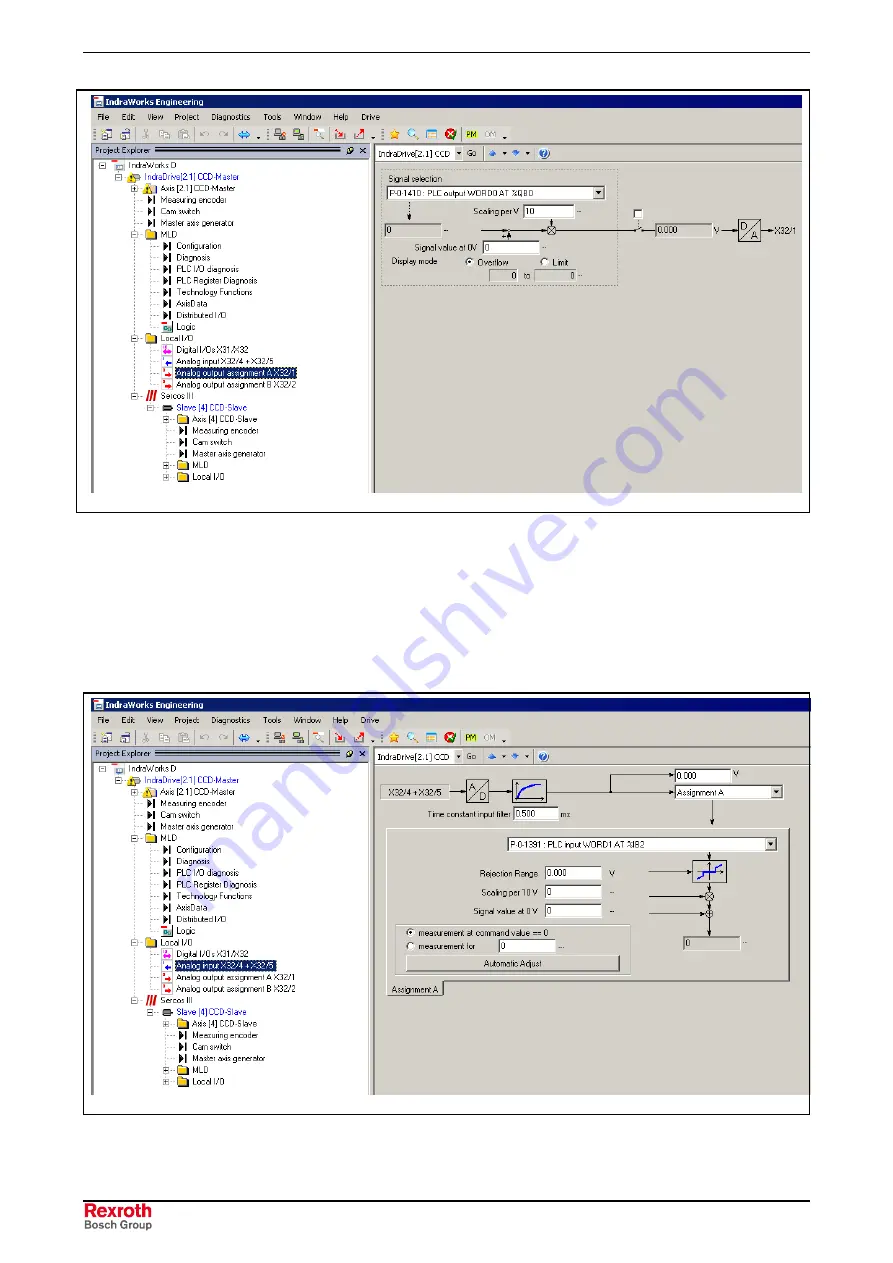
Fig. 5-13:

Assigning a parameter to an analog output

Reading in analog voltage values requires configuring the respective PLC
parameters (P-0-1390,...) for the analog inputs. The example below
illustrates the assignment of the PLC parameter "P-0-1391, PLC input
WORD1 AT %IB2" to analog input 1.

See also Functional Description "Analog Inputs"

DB000227v01_en.tif

Fig. 5-14:

Configuring an analog input in IndraWorks

Configuring Analog Inputs of

Control Section

Содержание REXROTH IndraMotion MLD

Страница 1: ...Summary Electric Drives and Controls Pneumatics Service Linear Motion and Assembly Technologies Hydraulics Rexroth IndraMotion MLD Getting Started R911319306 Edition 01 ...

Страница 2: ...f damages All rights are reserved in the event of the grant of a patent or the registration of a utility model or design DIN 34 1 The specified data is for product description purposes only and may not be deemed to be guaranteed unless expressly confirmed in the contract All rights are reserved with respect to the content of this documentation and the availability of the product Bosch Rexroth AG B...

Страница 3: ...ic Fields During Operation and Mounting 3 9 3 9 Protection Against Contact with Hot Parts 3 10 3 10 Protection During Handling and Mounting 3 10 3 11 Battery Safety 3 11 3 12 Protection Against Pressurized Systems 3 11 4 Preparation and Assembly 4 1 4 1 Step 1 Hardware and Firmware Requirements 4 1 Hardware Requirements 4 1 Firmware Requirements 4 1 4 2 Step 2 Install the Software 4 2 4 3 Step 3 S...

Страница 4: ... Step 10 Load and Activate the Program 6 6 Loading the Program 6 6 Starting the Program 6 7 Creating a Boot Project 6 7 6 4 Step 11 Test the Program 6 8 Online Display 6 8 Watching Variables with Trace Recording 6 9 Oscilloscope Function 6 9 7 Examples 7 1 7 1 MLD S Example of Application Sinusoidal Motion 7 1 Task Definition Application Description 7 1 Parameterizing Configuring the Drive 7 1 Pro...

Страница 5: ...e drive and create a simple PLC program for MLD S and MLD M The steps required for using Rexroth IndraMotion MLD for the first time are described below We distinguish the following phases Preparation and Assembly Commissioning Programming Note Assembly and commissioning are only required when Rexroth IndraMotion MLD is used for the first time ...

Страница 6: ...1 2 Introduction Rexroth IndraMotion MLD DOK IM MLD F STEP V KB01 EN P The figure below contains an overview of the required commissioning steps Fig 1 1 Commissioning Rexroth IndraMotion MLD ...

Страница 7: ...ases the guarantee and the right to payment of damages resulting from inappropriate use are forfeited The user alone carries all responsibility of the risks Before using Rexroth products make sure that all the pre requisites for an appropriate use of the products are satisfied Personnel that in any way shape or form uses our products must first read and understand the relevant safety instructions ...

Страница 8: ... To ensure an application specific use the drive controllers are available with differing drive power and different interfaces Typical applications of drive controllers belonging to the ECODRIVE03 family are handling and mounting systems packaging and foodstuff machines printing and paper processing machines and machine tools The drive controllers may only be operated under the assembly installati...

Страница 9: ... the person or persons responsible for the safe operation of this equipment If the equipment is resold rented or transferred or passed on to others then these safety instructions must be delivered with the equipment WARNING Improper use of this equipment failure to follow the safety instructions in this document or tampering with the product including disabling of safety devices may result in mate...

Страница 10: ...ments WARNING High electrical voltage due to wrong connections Danger to life or bodily harm by electric shock WARNING Health hazard for persons with heart pacemakers metal implants and hearing aids in proximity to electrical equipment CAUTION Surface of machine housing could be extremely hot Danger of injury Danger of burns CAUTION Risk of injury due to improper handling Bodily harm caused by cru...

Страница 11: ...gulations and requirements for the specific application as practiced in the country of use The equipment is designed for installation in industrial machinery The ambient conditions given in the product documentation must be observed Use only safety features and applications that are clearly and explicitly approved in the Project Planning Manual If this is not the case they are excluded The followi...

Страница 12: ...e instructions for installation in accordance with EMC requirements can be found in the documentation EMC in Drive and Control Systems The machine or installation manufacturer is responsible for compliance with the limiting values as prescribed in the national regulations Technical data connections and operational conditions are specified in the product documentation and must be followed at all ti...

Страница 13: ...me even for brief measurements or tests if the ground wire is not permanently connected to the points of the components provided for this purpose Before working with electrical parts with voltage higher than 50 V the equipment must be disconnected from the mains voltage or power supply Make sure the equipment cannot be switched on again unintended The following should be observed with electrical d...

Страница 14: ...safety conductor connection Prior to startups even for brief tests always connect the protective conductor or connect with ground wire Otherwise high voltages can occur on the housing that lead to electric shock 3 6 Protection Against Electric Shock by Protective Low Voltage PELV All connections and terminals with voltages between 0 and 50 Volts on Rexroth products are protective low voltages desi...

Страница 15: ...components software or firmware errors Dangerous movements can occur immediately after equipment is switched on or even after an unspecified time of trouble free operation The monitoring in the drive components will normally be sufficient to avoid faulty operation in the connected drives Regarding personal safety especially the danger of bodily injury and material damage this alone cannot be relie...

Страница 16: ...drive power connection by means of an emergency stop circuit or use a starting lockout to prevent unintentional start Make sure that the drives are brought to a safe standstill before accessing or entering the danger zone Safe standstill can be achieved by switching off the power supply contactor or by safe mechanical locking of moving parts Secure vertical axes against falling or dropping after s...

Страница 17: ...acemakers hearing aids and metal implants are not permitted to enter the following areas Areas in which electrical equipment and parts are mounted being operated or started up Areas in which parts of motors with permanent magnets are being stored operated repaired or mounted If it is necessary for a person with a heart pacemaker to enter such an area then a doctor must be consulted prior to doing ...

Страница 18: ...d Mounting Under certain conditions incorrect handling and mounting of parts and components may cause injuries CAUTION Risk of injury by incorrect handling Bodily harm caused by crushing shearing cutting and mechanical shock Observe general installation and safety instructions with regard to handling and mounting Use appropriate mounting and transport equipment Take precautions to avoid pinching a...

Страница 19: ...llers corresponding to the information in the respective Project Planning Manual must be provided with pressurized media such as compressed air hydraulic oil cooling fluid and cooling lubricant supplied by external systems Incorrect handling of the supply and connections of pressurized systems can lead to injuries or accidents In these cases improper handling of external supply systems supply line...

Страница 20: ...3 12 Safety Instructions for Electric Drives and Controls Rexroth IndraMotion MLD DOK IM MLD F STEP V KB01 EN P Notes ...

Страница 21: ...es requires the optional CCD module and the enabling of the functional firmware package ML Power section inverters HMS0 1 W0xxx converters HCS0 1 W0xxx Note Using the PLC functionality does not require any special optional card or control section configuration because it is a PLC that is running in parallel in the drive processor in the real time kernel Firmware Requirements Using the drive integr...

Страница 22: ...hat Rexroth IndraMotion MLD S is already enabled at the factory If the optional expansion package ML or TF is ordered subsequently the so called additional licensing is required i e the PLC functionality is subsequently enabled or licensed by the user See also Functional Description Functional Packages See also Functional Description Enabling of Functional Packages 4 2 Step 2 Install the Software ...

Страница 23: ... extension of drive functionality or stand alone single axis Motion Logic Control command triggering of the local axis with direct access to the device control of the drive see Command Triggering of the Local Axis MLD S direct access to all parameters of the drive via system wide PLC variables functions function blocks or a configurable synchronous channel direct access to the digital and analog i...

Страница 24: ...eans of corresponding Motion Control library according to PLCopen CCD cross communication interface to the remote axes on the basis of SERCOS III for motion command triggering of local and remote axes see Command Triggering of Local and Remote Axes MLD M connection of more inputs outputs I O modules or optional modules in the remote axes direct access to the digital and analog inputs outputs of th...

Страница 25: ...draWorks Select Connect online with IndraDrive serial Select serial interface Select device from List of all found devices and complete procedure with Finish DB000215v01_en tif Fig 4 3 Establishing connection via serial interface of PC to drive Establishing the Ethernet Connection to IndraDrive Requirements The following components and requirements are necessary to establish Ethernet communication...

Страница 26: ...he control panel the paragraph below describes how to do this When setting the IP address via the control panel observe the following points Switch on control voltage for IndraDrive controller For approx 8 s press both ESC and Enter keys at control panel With Up Down keys select 2 Comand and confirm selection with Enter key If you have to switch to parameter mode select 2 11 PM with Up Down keys a...

Страница 27: ...rks and establish serial communication with IndraDrive Fig 4 4 Establishing the connection with IndraWorks In IndraWorks open tree in project explorer window Right click IndraDrive hardware level in project explorer window and open Sercos III in pull down menu Fig 4 5 IP address setting In TCP IP Engineering Port area parameterize desired IP address network mask and default gateway Setting the IP ...

Страница 28: ...Ethernet communication to IndraDrive you have to assign an IP address and subnet mask for the unassigned Ethernet connection at your PC or laptop Call Windows Control Panel and open network properties by double clicking symbol Network and Dial up Connections Start Settings Control Panel Network and Dial up Connections Fig 4 6 Establishing the dial up connection By double clicking network connectio...

Страница 29: ...eparation and Assembly 4 9 DOK IM MLD F STEP V KB01 EN P If Microsoft Client has not yet been installed install Client via Install button Fig 4 7 Installing the client Select Internet Protocol TCP IP and click Properties button ...

Страница 30: ...sired IP address and Subnet mask Note It is not necessary to make an input for Default gateway Close all windows you have opened to parameterize the network card TCP IP Communication Between PC and IndraDrive With a standard Ethernet cable connect the engineering interface X26 at the IndraDrive control section to the Ethernet connection at your PC or laptop ...

Страница 31: ...is output Fig 4 10 Scan for Device You can parameterize the Ethernet communication connection via the button Scan for Device in order to search for an IndraDrive controller manually Parameterize the IP address window in which you want to scan for devices For IP port enter from 5002 to 5003 Note Pressing the button Default automatically sets the IP address range to 192 168 1 1 to 192 168 1 5 and th...

Страница 32: ...M MLD F STEP V KB01 EN P Fig 4 11 Settings for Ethernet communication IndraWorks now scans the IP range you parameterized for devices Fig 4 12 Display of devices found The preparations for establishing the connection can now be completed with the Finish button ...

Страница 33: ...N P Select Connect online with IndraDrive Ethernet and confirm selection with OK button Fig 4 13 Selecting the connection With the last communication settings IndraWorks tries to establish the connection to an IndraDrive controller via Ethernet Establishing Connection Automatically ...

Страница 34: ...4 14 Preparation and Assembly Rexroth IndraMotion MLD DOK IM MLD F STEP V KB01 EN P ...

Страница 35: ...nd PL the drive should be brought to a defined initial status See also Functional Description Load basic parameters 1 In order that basic parameters can be loaded you have to switch drive controller to parameter mode This can be done either directly via icon PM in toolbar or by right clicking Start parameterization level 1 Control panel display changes to PM DB000216v01_en tif Fig 5 1 Switching to...

Страница 36: ... V KB01 EN P 2 Call dialog for initial commissioning DB000217v01_en tif Fig 5 2 Load basic parameters Note For all other instructions on commissioning see online dialogs of DriveTop up to MP 02VRS or IndraWorks D as of MP 03VRS See also Functional Description Steps of Commissioning ...

Страница 37: ...kage Drive PLC Note Enabling the PLC requires licensing After you have selected the functional package Drive PLC and confirmed your selection a window containing information on the license agreement will open If you are interested in the function talk to your contact person in the Rexroth sales department Apply setting with Close Switch control voltage of drive off and on again Note The enabling o...

Страница 38: ...errors It is possible to control the behavior for errors which are generated by the corresponding PLC function blocks during command triggering of the axes With active reaction the drive error F2150 is generated The automatic reaction of the drive can be deactivated in this dialog Activation of the AxisData structure will be explained in detail under Data Channels Format adjustment for global regi...

Страница 39: ...n this dialog only makes sense in exceptional cases Normally this will be done in the programming system IndraLogic In the PLC IO Diagnosis dialog you can control the status of the process image of inputs and outputs Inputs assigned to the PLC are displayed in this dialog DB000221v01_en tif Fig 5 6 Dialog PLC IO Diagnosis Note The inputs which are not used in the PLC program are not displayed in I...

Страница 40: ... tif Fig 5 7 Dialog PLC Register Diagnosis This dialog is relevant only to the use of self contained technology functions without individual PLC programming This dialog allows configuring additional user defined command values and actual values which are to be transmitted via the AxisData structure see also MLD Data Channels PLC Register Diagnosis Technology Functions AxisData ...

Страница 41: ...ctivate it This is done in IndraWorks as described below Open CCD dialog Activate CCD by ticking it Select CCD mode MLD M in CCD system mode Set CCD cycle time Search for available slaves by clicking Scan button Select from slaves found and add to list Projected slaves Confirm configuration with Apply button DB000223v01_en tif Fig 5 8 Activating MLD M Activating MLD M System Mode ...

Страница 42: ...cal axis This axis is not displayed in dialog Fig 5 8 Cross Communication Drive Settings Axis 2 addresses the first projected slave axis address 4 in this exemplary dialog Axis 3 addresses the second projected slave axis address 7 in this exemplary dialog Axis 8 addresses the seventh projected slave Before MLD can take over motion command triggering for the master it must have control over the dri...

Страница 43: ...annels for cyclic data exchange between MLD and axes for acyclic parameter communication between MLD and axes to connect MLD to external control units or external control panels HMIs see also Getting Started VI Composer 02VRS Note As regards access to the local axis IndraMotion MLD S and IndraMotion MLD M do not differ As regards access to remote axes some specific features must be observed for In...

Страница 44: ... IM MLD F STEP V KB01 EN P DF000275v012_en tif Fig 5 10 Data channels of IndraMotion MLD for access to local and remote axes Based on a simplified device model the schematic diagram above shows the data channels starting at MLD Access to remote axes takes place via CCD ...

Страница 45: ...c access to axis parameters there are the following alternatives when using IndraMotion MLD S IndraMotion MLD M Direct variable channel Single and quick functional access from the PLC program to cyclically configurable S and P parameters in the drive It is only possible to access the local axis Parameter channel For acyclic access read and write to axis parameters of the local and remote axes by m...

Страница 46: ...LC 2 500 µs for ADVANCED before the PLC task For inputs which are read via the master communication or via CCD the update of the process image inputs is additionally delayed by the corresponding bus cycle time Update of process image outputs POI max TPLC 2 500 µs for ADVANCED after the PLC task For outputs which are written via the master communication or via CCD the update of the process image ou...

Страница 47: ...the PLC Digital inputs outputs of the control section are assigned to PLC parameters by assigning the desired bits of a PLC parameter to a digital input or output In IndraWorks a dialog is available for this purpose See also Functional Description Digital Inputs Outputs Fig 5 12 Configuring the digital inputs outputs in IndraWorks Outputting PLC variables via an analog output requires configuring ...

Страница 48: ...alog voltage values requires configuring the respective PLC parameters P 0 1390 for the analog inputs The example below illustrates the assignment of the PLC parameter P 0 1391 PLC input WORD1 AT IB2 to analog input 1 See also Functional Description Analog Inputs DB000227v01_en tif Fig 5 14 Configuring an analog input in IndraWorks Configuring Analog Inputs of Control Section ...

Страница 49: ...tion under MLD On the left side the dialog shows a selection of the process image parameters You have to enter the desired parameter of the process image The right side displays a selection of all inputs or outputs available on the slave The corresponding register of the I O module has to be entered Note The parameters set in this dialog are automatically added to the cyclic command values or actu...

Страница 50: ...its the corresponding terminals take effect See parameter setting of digital inputs outputs X31 X32 Furthermore the input word 0 P 0 1390 is assigned via P 0 0082 to the digital inputs of the MD1 module in slave 1 P 0 0303 contains 32 bits and therefore has to be assigned to a 32 bit process image register such as P 0 1440 DB000228v01_en tif Fig 5 15 Digital inputs of control section or MD1 and on...

Страница 51: ... corresponding terminals see parameterization of digital inputs outputs X31 X32 In this case it is possible that digital outputs of the slave control section are controlled by the PLC in the master and others by the slave drive itself Furthermore the output word 1 P 0 1411 is assigned via P 0 0081 to the digital outputs of the MD1 module in slave 1 In addition P 0 1412 is written to the analog out...

Страница 52: ...local axis are read via CCD by means of P 0 1441 to the input double word 26 In this way these digital inputs are read via the CCD mechanism at the same time as the inputs of remote axes As a result the local input takes effect at the same time as inputs which are read from remote axes via SERCOS III The same applies analogously to outputs on the local axis which have been configured via the CCD m...

Страница 53: ...annel is used when actual values or command values have to be exchanged consistently between PLC and local drive For the local axis MLD S it provides simple high performance cyclic data exchange Fields of application process controllers register controller winding computation realization of technology functions that require processing synchronous to the clock command value generators Note The real...

Страница 54: ...ll the cyclically configurable parameters contained in S 0 0187 List of configurable data in the AT and S 0 0188 List of configurable data in the MDT Note The remaining calculating time is automatically controlled If the time is exceeded an error is signaled at the function block output see also function block MX_SynchronControl For extended control and diagnosis of the real time channel there is ...

Страница 55: ... has to be activated AxisData is activated by the PLC configuration P 0 1367 bit 6 1 by default AxisData is not active DB000231v01_en tif Fig 5 19 Activating AxisData Note 1 When AxisData is used permanent control must have been activated for the local axis and for MLD M the MLD M system mode must have been additionally activated 2 After AxisData has been activated for the first time the drive has...

Страница 56: ...hronized dead time optimized command values processing for all axes in the MLD M system mode the local axis apart from the remote axes CCD slaves is commanded too in the CCD master via CCD SERCOS III The data contents of all axes are updated in the course of the MDT AT telegrams of cross communication CCD Thereby access to the axes CCD master and slaves takes place synchronously ...

Страница 57: ...n preparation If user specific command values and actual values are to be transmitted in addition to the preset actual values AxisData must be configured in the following dialog DB000233v01_en tif Fig 5 21 Dialog for setting the configurable elements of AxisData The parameters input in dialog MX_AXISDATA are automatically entered in the CCD configuration You can have the entire resulting list of c...

Страница 58: ...nts This is not necessary for normal motion tasks but can make sense for specific constellations Other cyclic actual values and command values can be configured in the IndraWorks dialog CCD Free process data Note The parameters set in this dialog are automatically added to the cyclic command values or actual values of the respective axis A list of all cyclic parameters can be seen in the CCD dialo...

Страница 59: ...out taking the detour via the process image The PLC source code therefore is very simple and clearly structured Note As in the case of processing of cyclic master communication data storage and limit value check or error handling is not carried out in this case Access via direct variables allows directly accessing all cyclically configurable parameters in the drive cf S 0 0187 List of configurable...

Страница 60: ... short for the local axis Access to parameters of remote axes is possible and uses the service channel of CCD in SERCOS III The result is that the function blocks have to be called several times and signal Done when transmission is over Several possibilities are provided for access to parameters Features of access to parameters via function faster than function block no instances no error control ...

Страница 61: ... block header in IndraLogic Addressing The parameters are addressed via constants from the base library FP_ The constants used in this library contain the SERCOS compatible address for S P parameters In the case of the function blocks of the base library the Ident or ParameterNumber input is supplied with these constants DB000253v01_en tif Fig 5 24 Addressing parameters via constants Parameter Cha...

Страница 62: ...rol unit or an external operator terminal e g BTV Note The global registers G0 G15 do not have any direct influence on the drive but only take effect in conjunction with MLD Parameter access via global registers is characterized by the following features 16 global registers P 0 1370 P 0 1385 with freely definable data format for parameterizing PLC functions or function blocks 2 global text registe...

Страница 63: ...rnal control unit via the master communication use as non volatile permanent memory for the MLD S because the contents are retained in case voltage fails In addition there are the two global registers P 0 1387 PLC Global Register AT0 and P 0 1387 PLC Global Register AT1 which are available as freely usable text parameters with a maximum of 255 characters plus closing 0 character Note The two globa...

Страница 64: ... carried out when MLD has control over the drive This can be done either permanently by activating the permanent control see Fig 5 4 or temporarily by the function block MX_SetControl Motion control via the PLC program is carried out by means of function blocks according to PLCopen For this purpose PLCopen has defined several IEC1131 function blocks by means of which the axes can be controlled Apa...

Страница 65: ... different dialogs for parameterizing the cyclic data Summary of all cyclic numerical data Motion data The parameters of the motion channel are automatically added to the cyclic parameters There are no inputs for this purpose MLD M I O The parameters required for exchanging data with remote I Os are entered There is the dialog for MLD M I O configuration for this purpose AxisData The parameters re...

Страница 66: ...rameterization Rexroth IndraMotion MLD DOK IM MLD F STEP V KB01 EN P Fig 5 28 Dialog displaying all cyclic data in preparation DB000238v01_en tif Fig 5 29 Dialog displaying the resulting configuration of the signal control word ...

Страница 67: ...splaying the signal status word The example below shows how the cyclic data of Motion AxisData I Os and free process data are summarized In the dialog on the right hand side all cyclic data are displayed When data are entered in the individual dialogs the configurations of the MDT AT data of the slave axes are automatically created ...

Страница 68: ...rbare Daten E A Daten parametrierbare Daten AxisData parametrierbare Daten Motiondaten fest definiert incl MUX Prozessdaten parametrierbare Daten zyklische Daten Bitzuweisungen Parameterzuweisungen Mit derBitzuweisung werden die Bits 12 bis 15 des Signalsteuerwortes konfiguriert Fig 5 31 Summary of the cyclic data ...

Страница 69: ...tem DB000240v01_en tif Fig 6 1 Logic node Calling the IndraLogic Programming System By double clicking the Logic node and each of its subnodes IndraLogic is opened globally or with the corresponding editor When started from IndraWorks the necessary communication settings for program download the target settings a main program PLC_PRG with task configuration 10 ms are automatically created in Indra...

Страница 70: ...project file as The IndraLogic project PRO file can be saved under a different name Note This generates a copy of the project IndraWorks still uses the current project The PLC project within IndraWorks can be re named in the properties Print project Prints the project components contained in IndraLogic Note Printing starts immediately on the standard printer Update The PLC structure data of IndraW...

Страница 71: ...rogramming 6 3 DOK IM MLD F STEP V KB01 EN P DB000292v01_en tif Fig 6 3 Importing an existing project PRO file Properties The dialog for the project properties of IndraLogic is only available when IndraLogic has not been opened ...

Страница 72: ...ate Program Creating a New Program The variables used in the program have to be declared and if necessary addressed to digital inputs or outputs DB000046v01_en bmp Fig 6 4 Working area of the main window declaration window and instruction section Declaring Variables and Writing Program ...

Страница 73: ...v01_en bmp Fig 6 5 Including a function block Blocks of the Program type have to be assigned to tasks Object Organizer Resources Task Configuration They determine for example on which time base and with which priority programs are called and processed DB000045v01_en bmp Fig 6 6 Task configuration Including a Function Block Changing Task Configuration ...

Страница 74: ...f an existing program is to be used it can be imported See also Importing an existing project PRO file 6 3 Step 10 Load and Activate the Program Loading the Program In IndraLogic carry out the menu command Online Login alternative shortcut Alt F8 Then there is a safety prompt you have to confirm with Yes in order to load the PLC program to the drive DB000243v01_en tif Fig 6 8 Loading the program C...

Страница 75: ... menu command Online Run alternative F5 DB000244v01_en tif Fig 6 9 Starting the program Creating a Boot Project To have the program written to the drive in storing form it must be saved as a boot project It is thereby available after the drive has been switched off and on again DB000245v01_en tif Fig 6 10 Creating a boot project ...

Страница 76: ...ite a new specific value to the variables after each cycle Online Force Values You can change the variable value in online operation by double clicking it Boolean variables thereby go from TRUE to FALSE or vice versa for all other variables you get the dialog Write variable xy in which you can edit the current variable value DB000047v01_en bmp Fig 6 11 Controlling and watching the PLC program with...

Страница 77: ...B000048v01_en bmp Fig 6 12 Trace recording Oscilloscope Function The oscilloscope function can be used to record drive internal and external signals and status variables parameter contents This function can be effectively used both for initial commissioning and debugging Its functionality can be compared to that of a 4 channel oscilloscope DB000246v01_en tif Fig 6 13 Starting the oscilloscope func...

Страница 78: ...6 10 Programming Rexroth IndraMotion MLD DOK IM MLD F STEP V KB01 EN P DB000291v01_en tif Fig 6 14 Oscilloscope function See also Functional Description Oscilloscope Function ...

Страница 79: ...ocity command value is mapped to parameter S 0 0036 Velocity command value To do this a sinusoidal command value is generated in this example and its periodic time and amplitude can be changed via a PLC variable Parameterizing Configuring the Drive Starting from the basic parameters you have to make some fundamental settings for the example of application sinusoidal motion The following paragraphs...

Страница 80: ...ples Rexroth IndraMotion MLD DOK IM MLD F STEP V KB01 EN P According to the mechanical configuration you have to set the scaling gear and feed constant DB000263v01_en tif Fig 7 2 Mechanical data Mechanical Data ...

Страница 81: ...rmanent control for the drive DB000264v01_en tif Fig 7 3 MLD configuration The digital inputs and outputs at X31 32 have to be parameterized at the drive as follows DB000265v01_en tif X31 3 P 0 1390 bit 0 IX0 0 bEnable Fig 7 4 Configuration of X31 at the drive MLD Configuration Configuration of Digital I Os ...

Страница 82: ...e enable AF via MC_Power DB000267v01_en tif Fig 7 6 Setting drive enable 3 Generate sine signal In the following program section the sine signal is generated The signal can be influenced via the following variables rAmplitude amplitude of sine signal rDurationSinePeriod periodic time of sine signal DB000268v01_en tif Fig 7 7 Generating sine signal 4 Travel sine profile The generated sine signal is...

Страница 83: ...load it to drive 2 Start drive PLC 3 Switch axis to operating mode OM Clear possibly present errors via Esc key 4 Switch power on Axis must show status Ab 5 Establish position data reference e g set absolute measuring 6 Application can be started via 1 signal at input I_1 at X31 of drive Visualizing and Diagnosing The signals can be watched either via the online display the IndraLogic trace functi...

Страница 84: ...7 6 Examples Rexroth IndraMotion MLD DOK IM MLD F STEP V KB01 EN P DB000270v01_en tif Fig 7 9 IndraLogic trace recording DB000271v01_en tif Fig 7 10 Oscilloscope recording in the drive ...

Страница 85: ...ital output and feedback digital input of the pneumatic picker are to be handled via MLD The procedure is to be started via a switch key which is read in at a digital input at the master Control close picker open picker and feedback picker closed for the pneumatic picker are to be controlled via digital I Os at the SERCOS slave This implies the additional task of accessing remote I Os by means of ...

Страница 86: ...he picker closes and takes up the product Step 2 When the picker has closed this is signaled by the feedback bPickerCloseAct P 0 1440 bit 1 IX50 1 and positioning to the place position is carried out In this case it is first the Y axis and then the X axis which is moved When the place position has been reached the output bPickerOpenCmd P 0 1411 bit 9 QX1 9 is set upon which the picker opens and pl...

Страница 87: ...ample of application Pick and Place The following paragraphs will explain these settings in short form To use MLD M the functional package Drive PLC must have been configured in the CCD master X axis Other optional functional packages are not required in CCD master X axis and CCD slave Y axis DB000272v01_en tif Fig 7 13 Enabling of functional package drive PLC Enabling of Functional Packages ...

Страница 88: ...on MLD DOK IM MLD F STEP V KB01 EN P According to the mechanical configuration you have to set the scaling gear and feed constant for the X and Y axis DB000273v01_en tif Fig 7 14 Example of mechanical data for X axis Mechanical Data ...

Страница 89: ... address 4 has been configured as CCD slave Y axis DB000274v01_en tif Fig 7 15 CCD settings The resulting axis addressing in MLD M is X axis axis address 2 Axis1 in MLD Y axis axis address 4 Axis2 in MLD In the drive PLC you have to select permanent control for the CCD master DB000275v01_en tif Fig 7 16 MLD configuration CCD Configuration MLD Configuration ...

Страница 90: ...t the X axis CCD master as follows DB000276v01_en tif X31 3 P 0 1390 bit 0 IX0 0 bStartAutomatic X31 4 P 0 1390 bit 1 IX0 1 bProgramReset Fig 7 17 Configuration X31 of X axis CCD master DB000277v01_en tif X32 3 P 0 1410 bit 0 QX0 0 bPickerActive Fig 7 18 Configuration X32 of X axis CCD master Configuration of Digital I Os at the Master ...

Страница 91: ...f the input is copied directly from parameter P 0 0303 signal status of the digital inputs to the CCD master see also Fig 7 21 DB000279v01_en tif X32 6 P 0 0304 bit 8 bPickerCloseCmd X32 7 P 0 0304 bit 9 bPickerOpenCmd Fig 7 20 Configuration X32 of Y axis CCD slave The digital outputs only have to be configured as outputs and a dummy parameter can be assigned to them as is done for the inputs The ...

Страница 92: ...le of application P 0 1410 is written by MLD M By the above mentioned configuration this parameter directly takes effect at the status of the digital outputs P 0 0304 in the Y axis CCD slave The status of the digital inputs of the CCD slave P 0 0303 is copied to parameter P 0 1440 of the CCD master and evaluated there in MLD M As P 0 0303 is a 32 bit value it has to be assigned to a 32 bit process...

Страница 93: ...s DB000281v01_en tif Fig 7 22 Variable declaration 2 Initialization In the first initialization step all variables or function blocks are brought to a defined status DB000282v01_en tif Fig 7 23 Initialization 3 Generate start edge After a positive edge at input bStartAutomatic P 0 1390 bit 0 IX0 0 the automatic sequence of steps is processed DB000283v01_en tif Fig 7 24 Starting the Pick and Place ...

Страница 94: ...ck position In the second step step 10 it is first the X axis and then the Y axis which position to pick position When the 1st positioning process of both axes has been completed the output bPickerCloseCmd P 0 1411 bit 8 QX1 8 is set whereby the picker closes and takes up the product When the picker has closed this is signaled by the feedback bPickerCloseAct P 0 1440 bit 1 IX50 1 and the program s...

Страница 95: ...is set upon which the picker opens and places the product The input bPickerCloseAct P 0 1440 bit 1 IX50 1 signals that the picker has opened and the program switches to the next step DB000286v01_en tif Fig 7 27 Step 20 positioning to place position 7 Position to start position In the fourth step step 30 it is first the Y axis and then the X axis which positions to start position When the travel pr...

Страница 96: ...nce of steps are reset The sequence of steps has to restart Step 40 has been prepared for further functionality and can be included by the corresponding changes in the program Step 99 has been prepared for an error reaction but this reaction has not been programmed in the example of application DB000288v01_en tif Fig 7 29 Step 100 resetting the sequence of steps ...

Страница 97: ...to operating mode OM Clear possibly present errors via Esc key 4 Switch power on Axes must show status Ab 5 Establish position data reference for both axes e g set absolute measuring 6 Application can be started via input I_1 at CCD master Visualizing and Diagnosing The signals can be watched either via the online display the IndraLogic trace function or the oscilloscope function of the drive DB00...

Страница 98: ...7 20 Examples Rexroth IndraMotion MLD DOK IM MLD F STEP V KB01 EN P DB000290v01_en tif Fig 7 31 Oscilloscope recording of X axis ...

Страница 99: ...ring MLD 5 4 Creating a boot project 6 7 Creating a new program 6 4 Cyclic data channels 5 11 D Data channel I O channel 5 12 Parameter channel 5 26 Direct variables 5 25 E Establishing the Ethernet connection to IndraDrive 4 5 Establishing the serial connection to IndraDrive 4 5 Explanation of the MLD data channels 5 12 F Firmware requirements 4 1 Free process data in MLD M 5 24 G General informa...

Страница 100: ...rpose 5 28 PLC parameters for general purpose global registers 5 28 Programming 6 1 R Requirements 4 5 S Safety Instructions for Electric Drives and Controls 3 1 Setting IP address and network mask in PC 4 8 Starting the program 6 7 hardware and firmware requirements 4 1 Load and activate the program 6 6 Test the program 6 8 Install the software 4 2 Structure of the drive system 4 3 Establish comm...

Страница 101: ...Rexroth IndraMotion MLD Index 8 3 DOK IM MLD F STEP V KB01 EN P V W Watching variables with trace recording 6 9 ...

Страница 102: ...CD group Local axis for MLD S is the axis of the drive and for MLD M it is the axis in the drive with the CCD option SERCOS III master interface For MLD M remote axes are the axes in the CCD slaves The drive contains a master axis generator It can be controlled similarly to a real axis and then simulates an axis motion The position of this master axis can be used as input for the local and remote ...

Страница 103: ...9 2 Glossary Rexroth IndraMotion MLD DOK IM MLD F STEP V KB01 EN P ...

Страница 104: ...V KB01 EN P R911319306 Bosch Rexroth AG Electric Drives and Controls P O Box 13 57 97803 Lohr Germany Bgm Dr Nebel Str 2 97816 Lohr Germany Phone 49 0 93 52 40 50 60 Fax 49 0 93 52 40 49 41 service svc boschrexroth de www boschrexroth com ...

Отзывы: