5-8
Commissioning and Parameterization
Rexroth IndraMotion MLD
DOK-IM*MLD-F*STEP**V**-KB01-EN-P
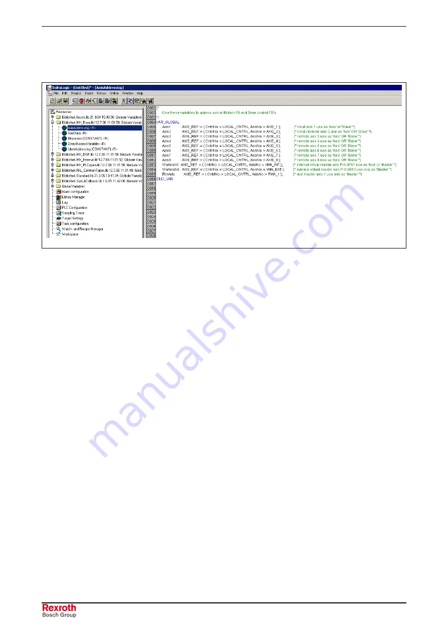
All listed axes can be addressed via MLD-M. The axis addressing to be
set in the PLC is based on the order of projected slaves. In the
programming interface the axis addresses have already been generated
as global variables:
DB000224v01_en.tif
Fig. 5-9:
Axis addressing in IndraLogic
Addressing takes place as follows:
•
"Axis 1" always addresses the local axis.
This axis is not displayed in dialog Fig. 5-8 "Cross Communication
Drive Settings".
•
"Axis 2" addresses the first projected slave
(axis address 4 in this exemplary dialog)
•
"Axis 3" addresses the second projected slave
(axis address 7 in this exemplary dialog)
•
…
•
"Axis 8" addresses the seventh projected slave
Before MLD can take over motion command triggering for the master, it
must have control over the drive. This can be done in the following ways:
•
permanently via setting "PLC has permanent control over the drive"
(see Fig. 5-4)
(standard setting when using MLD-M) or
•
temporarily via function block "MX_SetControl"
Axis Addressing
Controlling the Drive
Содержание REXROTH IndraMotion MLD
Страница 34: ...4 14 Preparation and Assembly Rexroth IndraMotion MLD DOK IM MLD F STEP V KB01 EN P ...
Страница 101: ...Rexroth IndraMotion MLD Index 8 3 DOK IM MLD F STEP V KB01 EN P V W Watching variables with trace recording 6 9 ...
Страница 103: ...9 2 Glossary Rexroth IndraMotion MLD DOK IM MLD F STEP V KB01 EN P ...


