MIC Series IP Power Supply
Installation | en
23
Bosch Security Systems, Inc.
User Manual
F.01U.265.804 | 1.6 | 2012.08
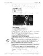
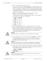
27. Test the washer by pressing the red button marked SW1 PUMP ON on the PCB.
LED 3 illuminates in response to telemetry commands from the control room to turn on
the washer. Note that the software in the camera prevents the washer from running more
than 10 seconds continuously to prevent emptying the washer bottle.
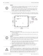
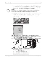
28. Verify that the thermal pads are in the correct position on the encoder or on the built-in
stand-offs on the inside of the lid of the enclosure. Correct positioning of the thermal
pads is imperative, or the encoder may not function. See the photos below for the
correct positioning.
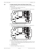
Figure 3.9
Thermal pads in correct position on the encoder
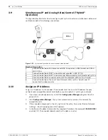
Figure 3.10
Location of correct position for thermal pads on the inside of the lid of the enclosure
29. After all wiring and connections are complete, connect the power supply to the power
source. The PSU should now have power and be operational.
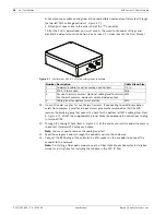
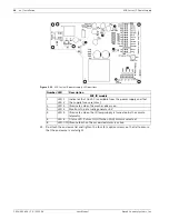
30. Verify that the following LEDs are lit on the PCB (depending on the model of MIC PSU):
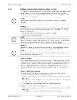
Figure 3.11
MIC Series power supply LED position (at the "top right" of the PCB)
NOTICE!
For installation of the MIC Washer Kit (MIC-WKT), MIC 8-input Alarm Card (MIC-ALM) or
Biphase converters (MIC-BP3 or MIC-BP4), please see their respective manuals.
Number LED
Description
MIC Non-IR models
1
LED 2 18 VAC power on to camera
2
LED 4 Power on for optional heater
3
LED 3 18 VAC power on camera
4
LED 5 Power on for optional heater
Содержание MIC IP PSU
Страница 1: ...MIC Series IP Power Supply MIC IP PSU en User Manual ...
Страница 2: ......
Страница 99: ......


