Assembly Instructions
Hardware Required
Front
Rear
Please Note that the
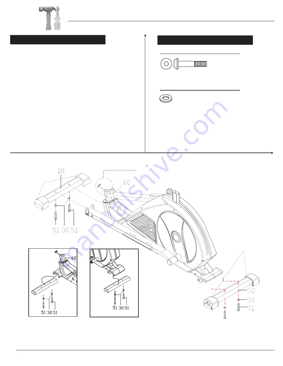
Front Stabilizer (#18)
has roller
wheels that spin for ease of relocating the unit and the
Rear Stabilizer (#52)
has height adjustable caps
for leveling of the unit.
Bolts
#51. Bolt (M8x50x20xS6 mm)
[4 Pieces]
Washers
#30. Washer (d8xφ16x1.5 mm)
[4 Pieces]
A s s e m b l y S t e p 1
BRM8981
With the help of an assistant, attach the
Front Stabilizer
(#18)
to the front of the
Main Frame (#60)
by inserting two
Bolts (#51)
through two
Washers (#30)
and up through
the
Front Stabilizer (#18)
.
Next, attach the
Rear Stabilizer (#52)
to the back of the
Main
Frame (#60)
by inserting two
Bolts (#51)
through two
Washers (#30)
and up through the
Rear Stabilizer (#52)
.
Remove the
Bolts (#51), Washers (#30)
and Tubes that
are pre-assembled on the bottom of the front and rear
of the
Main Frame (#60)
and set them aside. The Bolts
and Washers will be used later in this step. The two tubes
are the packing material to protect the production.
Roller Wheels
(front of caps)
Height Adjustable Caps
(bottom of caps w/
side adjustment dials)
Make sure this wire is exposed and hanging out before proceeding
to the next step. If it has fallen inside the tube, use a
bent wire to “fish” it out.
Page 6


