background image

2

Operating Instructions and Parts Manual

www.blueangelpumps.com

GENERAL SAFETY INFORMATION (CONTINUED)

13.  Make sure the line voltage and frequency of electrical current supply 

agrees with the motor wiring.

14.  Do not attempt repairs to the electric motor. All repairs to the motor 

must be completed at a licensed or certified electrical motor repair 
shop.


Do not touch an operating motor. Modern 

  motors are designed to operate at high 

temperatures.

15.  Avoid kinking electrical cord and protect electrical cord from sharp 

objects, hot surfaces, oil and chemicals. Replace damaged or worn 
cords immediately.

16.  Keep fingers and foreign objects away from ventilation and other 

openings. Do not insert any objects into the motor.


Risk of electric shock! Never connect the green 

  (or green and yellow wire) to a live terminal! 

17.  Use wire of adequate size to minimize voltage drop at the motor.


Do not handle pump or pump motor with wet 

    hands, when standing on a wet or damp surface 

or when standing in water. Fatal electrical shock will occur.
 

Pump motor is equipped with an automatic

  resetting thermal protector and may restart 

unexpectedly. Protector tripping is an indication of motor overheating 

because of operating pump at low heads (low discharge restriction), 

excessively high or low voltage, inadequate wiring, incorrect motor 

connections,excessive surrounding air temperature, inadequate 

ventilation, and/or defective motor or pump.

PRE-INSTALLATION

WATER SUPPLIES

The water supplies illustrated in Figure 16 (on page 10) are possible 
sources for water. These water supplies can be divided into two 
categories:
SURFACE WATER
Water from a lake, stream, pond and cistern. This water is usually not fit 
for human consumption, but may be suitable for washing, irrigation or 
other household uses.
GROUND WATER
Water found in the water bearing stratum at various levels beneath the 
earth. Of all the fresh water found on earth only 3 percent is found on the 
surface and 97 percent is underground.

TANKS - CONVENTIONAL STORAGE

The function of the tank is to store a quantity of water under pressure. 
When full, the tank contains approximately 2/3 water and 1/3 
compressed air. The compressed air forces the water out of the tank 
when a faucet is opened. An air volume control automatically replaces air 
lost or absorbed into the water. The usable water, or draw-down capacity, 
of the tank is approximately 1/6 of the tanks total volume when operated 
on a “20-40” pressure setting (Figure 1).

TANKS - PRE-CHARGED STORAGE

A pre-charged storage tank has a flexible bladder or diaphragm that acts 
as a barrier between the compressed air and water. This barrier prevents 
the air from being absorbed into the water and allows the water to be 
acted on by compressed air at initially higher than atmospheric pressures 
(pre-charged). More usable water is provided than with a conventional 
type tank. Pre-charged tanks are specified in terms of a conventional 
tank. For example, a 20 gallon pre-charged tank will have the same 
usable water or draw-down capacity as a 40 gallon conventional tank, 
but the tank is smaller in size (Figure 1).

PRESSURE SWITCH

The pressure switch provides for automatic operation. The pump starts 
when pressure drops to a cut-in setting. The pump stops when pressure 
reaches a cut-out setting.

WELLS

A new well should be pumped clear of sand before installing the pump. 
Sand will damage the pumping parts and seal. The draw-down level of 
the well should not exceed the maximum rated depth for the pump. The 
capacity of the pump will be reduced and a loss of prime may occur.

INSTALLATION

LOCATION

Select a location as close to the water supply as possible.
Be sure to comply with any state or local codes regarding the placement 
of the pump. The equipment must be protected from the elements. A 
basement or heated pump house is a good location. Make sure the 
pump has proper ventilation. The temperature surrounding the pump is 
not to exceed 100° F (38°C) or nuisance tripping of the motor overload 
may occur.


This pump is designed for indoor installation 

  only. Failure to install indoors will significantly 

increase the risk of injury or death from electrical shock.

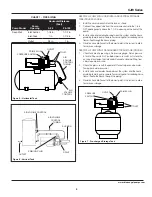
Figure 1 - Conventional and Pre-charged Storage Tanks

AIR VOLUME 
CONTROL

CONVENTIONAL TANK

PRE-CHARGED TANK

BLADDER

Содержание 100CJW

Страница 1: ...ious injury Disconnect power and release all pressure from the system before attempting to install service relocate or perform any maintenance Lock the power disconnect in the open off position Tag th...

Страница 2: ...is to store a quantity of water under pressure When full the tank contains approximately 2 3 water and 1 3 compressed air The compressed air forces the water out of the tank when a faucet is opened An...

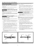
Страница 3: ...5 feet vertically of the water level See converting to shallow well pump on page 6 Shallow well installations have only one pipe between the pump and water supply Figure 2 DRILLED WELL FIGURE 16 1 Ins...

Страница 4: ...E AND SPRING WITH TWO PIPE JET FIGURE 16 ON PAGE 10 1 Install a 1 1 4 in foot valve not included to the jet body A 1 1 4 in coupling is required to connect the larger pipe to the jet assembly 2 Connec...

Страница 5: ...TANK FIGURE 7 1 Check tank pre charge using a tire pressure gauge Set air pressure in tank to 28 psi which is 2 psi below pressure switch cut in level An air valve is located on the side and will acc...

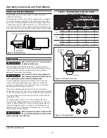
Страница 6: ...re used run a wire directly to the metal well casing or use a ground electrode furnished by the power company There is only one proper ground terminal on the unit The terminal is located under the pre...

Страница 7: ...INTENANCE Disconnect power and release all pressure from the system before attempting to install service relocate or perform any maintenance Lock the power disconnect in the open off position Tag the...

Страница 8: ...y attention to how the original shaft seal is installed before disassembly 10 Remove the shaft seal from the impeller make sure the stainless steel sleeve comes off the impeller all you should see on...

Страница 9: ...plastic cap over the motor shaft end 21 Reassemble the diffuser make sure the arrow indicating the top is pointed toward the top of the pump torque the two screws to 30 10 inch pounds 22 Using the 4 c...

Страница 10: ...in D DRIVEN WELL Pipe with a pointed screen is driven into the ground below the water table The depth is usually less than 50 feet Available diameters are 1 through 2 E DRILLED WELL A hole bored into...

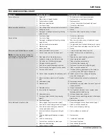
Страница 11: ...ace as necessary 6 Clogged nozzle deep well 6 Pull jet and clear obstruction 7 Air volume control diaphragm ruptured 7 Replace air volume control See Page 6 8 Foot valve may be clogged or stuck closed...

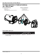
Страница 12: ...f any Part description and number as shown in parts list Address parts correspondence to Wayne Water Systems 101 Production Drive Harrison OH 45030 U S A 13 REPLACEMENT PARTS LIST Ref No Part Number f...

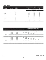
Страница 13: ...528 384 588 444 330 264 234 Jet Diameter Pump Model No Jet Assembly No Vertical Distance to Pumping Level 30 40 50 60 70 80 90 100 Output in Gallons Per Hour GPH 2 in 50CJW 50CJW 56319 55462 620 590...

Страница 14: ...14 Operating Instructions and Parts Manual NOTES www blueangelpumps com...

Страница 15: ...15 NOTES www blueangelpumps com CJW Series...

Страница 16: ...HATSOEVER IS EXCLUDED Some states do not allow limitations on how long an implied warranty lasts or do not allow the exclusions or limitations of incidental or consequential damages so the above lim i...

Страница 17: ...al manipular este producto y l vese las manos despu s de manipularlo SEGURIDAD GENERAL 1 Lea con atenci n el manual de instrucciones incluido con este producto Familiar cese bien con los controles y...

Страница 18: ...PRE INSTALACI N FUENTES DE SUMINISTRO DE AGUA Las posibles fuentes de suministro de agua se ilustran en la Figurra 16 en la p gina 27 Se pueden clasificar en dos categor as AGUAS DE SUPERFICIE Agua de...

Страница 19: ...ndo se necesite dar servicio o almacenarlas Una manguera de caucho instalada entre el sistema de agua y la tuber a de la casa reducir el ruido que se transmite a la casa Se pueden usar tuber as de pl...

Страница 20: ...siempre sumergida Figura 3 Eyeccion de Chorro por Dos Tubos CUERPO DEL EYECTOR DE CHORRO V LVULA DE ASPIRACI N TUBER A DE 3 2 CM 2 54 CM 1 PULG PIPE TUBER A DE 3 2 CM Figura 4 Chorro de 1 Tubo TAMP N...

Страница 21: ...ecci n del tubo y baje el eyector de chorro dentro del pozo 4 Agregue tuber a hasta que el eyector de chorro est entre 1 52 y 4 57 m 5 y 15 pies por debajo del nivel de agua m s bajo que se anticipa N...

Страница 22: ...ores Seleccione los alambres y el fusible del tama o adecuado Tabla 2 Para la protecci n del circuito del motor se recomiendan los fusibles que interrumpen por un tiempo en vez de los fusibles convenc...

Страница 23: ...el motor y vuelva a llenar la bomba con agua El tiempo necesario para cebar es proporcional a la cantidad de agua en la tuber a de ingreso No permita que la bomba se caliente 6 Deje que el sistema fun...

Страница 24: ...conectar la corriente el ctrica a la bomba NOTA Conforme la bomba vuelve a llenar el tanque con agua el control de volumen de aire suministra al tanque la relaci n adecuada de aire y agua para que el...

Страница 25: ...mpulsor sobre el eje del motor apriete a mano Lubrique la nariz del impulsor con lubricante seguro para agua potable 20 Vuelva a colocar la tapa de pl stico sobre el extremo del eje del motor 21 Vuelv...

Страница 26: ...Sp 26 Manual de instrucciones de funcionamiento y piezas de repuesto NOTAS www blueangelpumps com...

Страница 27: ...rra por debajo de la capa fre tica La profundidad por lo general es menor a 15 25 m 50 pies Los di metros comunes fluct an entre 2 5 cm 1 y 5 1 cm 2 E POZO PERFORADO Un hoyo perforado en la tierra con...

Страница 28: ...a de la bomba 1 Baje m s el tubo de succi n dentro del pozo 2 La v lvula de control est demasiado abierta pozos profundos 2 Ajuste la v lvula de control o repita el procedimiento de cebado 3 Al cebar...

Страница 29: ...nectado a la salida incorrecta de la bomba 3 Mueva a la apertura correcta de la bomba 4 Precarga de tanqueincorrecta Tanque precargado 4 Agregue o quite aire cuanto sea necesario 5 Diafragma o bolsa r...

Страница 30: ...respondencia a N mero del modelo BLue Angel Pumps C digo impreso 101 Production Drive Descripci n y n mero del repuesto seg n la lista de repuestos Harrison OH 45030 U S A LISTA DE PARTES DE REPARACI...

Страница 31: ...2673 2018 1500 1200 1064 Di metro del Charro Modelo de Bomba No Ensamblado del Chorro No Distancia Vertical al Nivel de Bombeo En Metres 9 1 12 2 15 2 18 3 21 4 24 4 27 4 30 5 Entrega en Litros por Ho...

Страница 32: ...EXCLUS Certaines Provinces n autorisent pas de limites de dur e pour les garanties implicites ni l exclusion ni la limite des dommages fortuits ou indirects Les limites pr c dentes peuvent donc ne pa...

Отзывы: