background image



























11

®

3  For each of the remaining switch boxes (if used), use a serial cable with RJ9 

connectors at both ends (see 

Appendix 3

 for specification). Connect one 

end to the socket marked ‘OUT’ of the previous box and the other end to 
the socket marked ‘IN’ of the next box. 

4  Set the addressing switches on each switch 

box using the two small switches marked 
‘Slct’ on the front panel. The box connected 
directly to the ServSwitch Duo IPC is Box 1 
and so on down the daisy-chain line to Box 
4 at the end.

5  Connect IEC to IEC power leads between 

each port and the power input socket 
of each computer that requires power 
switching. Carefully note to which power 
ports, on which boxes, each computer is connected. If server systems have 
multiple power inputs, then each input must be connected via separate 
ports, which can be on the same, or different boxes.

6  Connect each box to a suitable mains power input. 

Now proceed to the configuration stage covered in the 

Power switching 

configuration

 section within the Configuration chapter.

To connect and address the switch boxes

Note: The ServSwitch Duo IPC can be powered on during this procedure, 
however, the switch boxes should be switched off.

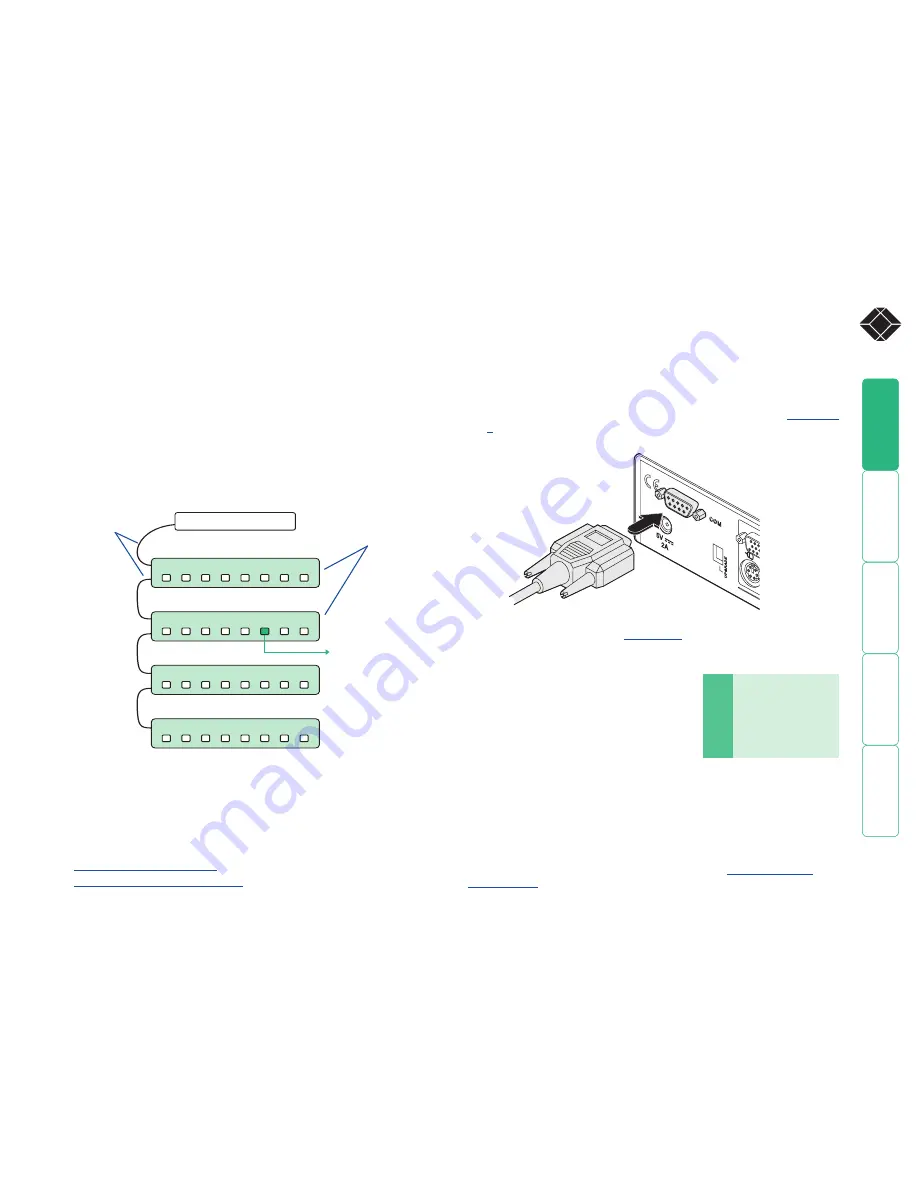
1  Mount up to four switch boxes in positions where they are close to the 

computers that they will control and not too distant from the ServSwitch 
Duo IPC (preferably within 8 feet).

2  Use a serial cable with an RJ9 and a 9-pin D-type connector (see 

Appendix 

3

 for specification). Connect the RJ9 plug to the socket marked ‘IN’ on the 

first switch box. Connect the other end to the socket marked ‘COM’ on the 
ServSwitch Duo IPC. 


Box

   Switch 1  Switch 2


1

          Off 

Off


2

          On 

Off


3

          Off 

On


4

          On 

On

Off = switch upwards
On = switch downwards
Switch 1 is on the left side

Power switching connections

A key feature of the ServSwitch Duo IPC is its ability to remotely control the 
power of the computers attached to it. The actual power switching process 
requires the use of optional switch boxes, however, the ServSwitch Duo 
IPC offers the control port for these switches and the necessary operational 
integration within its menu system.
The control connector of the first power switch is connected, via serial cable, 
to the rear panel of the ServSwitch Duo IPC. Any additional power switches are 
then connected via a ‘daisy-chain’ arrangement to the first power switch. Each 
power switch box is then given a unique address and access to each power port 
(8 ports on each power switch box) is gained using a combination of the switch 
box address and the port number. 
Each power port can then be connected to the power inputs of each computer 
and each power switch box then connected to a mains power supply.

IMPORTANT: Power switching devices have a maximum current rating. It is 
essential to ensure that the total current drawn by the equipment connected 
to the power switching device does not exceed the current rating of the power 
switching device. You must also ensure that the current drawn from any mains 
socket does not exceed the current rating of the mains socket.

Setting up, configuring and using power switching requires three main steps:

•  Connect and address the switch boxes 

ð


•  

Configure the power strings

•  

Operate remote power switching

8

IN

IN

IN

IN

OUT

OUT

OUT

8

8

8

7

7

7

7

6

6

6

6

5

5

5

5

4

4

4

4

3

3

3

3

2

2

2

2

1

1

1

1

ServSwitch Duo IPC

Power to computer
Box 2, port 6 - address: 26

Box 1

Box 2

Box 3

Box 4

Power 
switch 
boxes

‘Daisy-chain’ 
control 
connections

COM

5V

2A

Содержание ServSwitch Duo IPC KV6216FA-R2

Страница 1: ...n the U S Call 877 877 BBOX outside U S call 724 746 5500 FREE technical support 24 hours a day 7 days a week Call 724 746 5500 or fax 724 746 0746 Mailing address Black Box Corporation 1000 Park Driv...

Страница 2: ...nks to cascaded computers 15 Multiple video head connections 16 Configuration Overall initial configuration 17 Configuration menus 18 Configuration menus layout 19 Registering users 20 Registering com...

Страница 3: ...ems 37 Setup Options 37 Global Preferences 38 User Preferences 40 Advanced Options 42 Appendix 2 Firmware upgrade 43 Appendix 3 Cable and connector specifications 45 RS232 serial mouse to PS 2 convert...

Страница 4: ...also allow direct connection to the Internet A second Wizard IP can be added to the other user port to provide even greater remote connectivity The Wizard IP also provides a local user connection port...

Страница 5: ...t in length EHN408 0020 20 feet in length PS 2 to USB flash cables Required to connect with computers that use a USB port to connect their keyboard and mouse Part numbers EHN428 0006 6 feet in length...

Страница 6: ...rackets and mount the unit within the frame before connecting any cables To attach the rack mount brackets 1 On either side of the ServSwitch Duo IPC casing position a rack mount bracket with the slot...

Страница 7: ...s available at the rear of the ServSwitch Duo IPC Each port consists of three sockets to accommodate a keyboard a video monitor and a mouse Keyboard and mouse mode logging The ServSwitch Duo IPC maint...

Страница 8: ...and video plugs to the three sockets of the chosen COMPUTER PORT at the rear of the ServSwitch Duo IPC PS 2 keyboard Sun keyboard Right Ctrl F1 Stop Right Ctrl F2 Again Right Ctrl F3 Props Right Ctrl...

Страница 9: ...yboards have a power key which will be mapped to perform the same function for a Sun computer PS 2 keyboard Apple keyboard Left Ctrl Left Control Left Win Start Left Command Left Alt Left Option alt R...

Страница 10: ...eir operating system It is necessary for the ServSwitch Duo IPC to be attached and powered on during this sequence so that it can give the required responses and keep track of all modes and settings r...

Страница 11: ...e plugs at one end of the KVM cable set to the keyboard video and mouse sockets at the rear of the Wizard IP collectively labelled COMPUTER KVM SWITCH 3 Connect the plugs at the other end of the KVM c...

Страница 12: ...h 2 1 Off Off 2 On Off 3 Off On 4 On On Off switch upwards On switch downwards Switch 1 is on the left side Power switching connections A key feature of the ServSwitch Duo IPC is its ability to remote...

Страница 13: ...y connecting other KVM switches to the ServSwitch Duo IPC The combination of switches can be arranged up to four levels deep forming a tree or cascade arrangement with computers situated at any level...

Страница 14: ...then be allocated to users according to their general availability in that group not as specific individual lines To do this each link group has an access number which is determined by the ports to w...

Страница 15: ...may be carried out in any order but for clarity this instruction will begin at the higher level switch here called the upper switch i e the one that is being fed into by a switch at the cascade level...

Страница 16: ...displays the computer names and does not require any knowledge of port addresses some of which as discussed above can be up to eight digits long See the Selecting cascaded computers section in the Ope...

Страница 17: ...he ServSwitch Duo IPC switches its channel if it receives the same command on its serial interface Consequently by linking the serial interfaces a master unit may be made to automatically switch one o...

Страница 18: ...ges If you intend to use security then it is important to allocate a password to the ADMIN account 3 Create user accounts and allocate access rights Use the ADMIN account to add user profiles password...

Страница 19: ...hange the standard hotkeys for one of the devices as they both use and as their standard hotkeys It is not important which device is altered however ensure that the new setting does not clash with any...

Страница 20: ...Enter an appropriate password for the ADMIN user account with regard to the following The password can be up to 12 characters long The password can use letters numerals and or certain punctuation mar...

Страница 21: ...mputer entries 1 Display the Configuration menu Note You must be logged in as the ADMIN user 2 Highlight Edit Computer List and press 3 Either Create a new computer entry Press and enter a new name or...

Страница 22: ...computers are active There are up to three steps that need to be configured to use autoscanning Select the autoscan mode Scan List Active PCs or All PCs Select the autoscan period This is the time tha...

Страница 23: ...ill send the configuration data to your computer The XPREAD program will store the data in a file named XPRODATA CSV that will be created in the same directory where the XPREAD program was started Ens...

Страница 24: ...osition 3 Press the USER and the COMPUTER keys together 4 The green USER display will show for a few seconds to confirm that a reset is taking place 5 Return switch 2 to the normal OFF position up Ens...

Страница 25: ...mouse The IntelliMouse format was introduced to support among other features the scroll wheel function If the mouse has a scroll wheel then it is likely to support the IntelliMouse format If it is a M...

Страница 26: ...lay 3 Press and hold down the USER key for 5 seconds until the green USER display goes off The keyboard and mouse will then be powered off 4 As soon as the green display goes off release the USER key...

Страница 27: ...highlighted press 3 Press to display the Advanced Options menu 4 Highlight the Power Control option and press Check that the Power Control option is ENABLED If not highlight it and press to change it...

Страница 28: ...ings The string editing screen has two editing areas where you can enter and view the power switch code as either ASCII characters or HEX values Power String ASCII Edit Power ON String 1 P18 1 Power S...

Страница 29: ...ServSwitch Duo IPC synchronisation features together but this requires a specially constructed serial cable Please contact Black Box for further details Display Data Channel DDC The industry standard...

Страница 30: ...the configuration and selection of systems within a complex cascade structure It also provides excellent security control as unauthorised users are prevented from achieving what is sometimes possible...

Страница 31: ...computer port selected will then be connected to the user port that is currently chosen by the adjacent user button and green numeric indicator User button and numeric indicator These items allow you...

Страница 32: ...he sixteen or eight standard computer ports there are also two additional special ports that appear after port 16 and before port 1 This port provides no video signal so that a connected power saving...

Страница 33: ...er release all of the keys If the port address is two or more characters release the first numeral key and press the second repeat this procedure until all of the port address numerals have been enter...

Страница 34: ...P login and password are required in addition to and in advance of these details see Logging in and out for more details If the security option has been selected by your administrator then you will be...

Страница 35: ...ort using the front panel buttons If you are not already logged in do so now 2 Press to select More menus 3 Highlight the User Preferences option and press to select 4 Highlight the Confirmation Box o...

Страница 36: ...e needed by the computer to access its BIOS setup area during the bootup sequence Routing status On occasions it may be useful to know which computers are being accessed in which modes and by whom The...

Страница 37: ...itch port s to which the computer is connected Check the indicator status for that those ports on the power switch front panel do they illuminate extinguish when the switching command is sent If a mul...

Страница 38: ...ERTY format When the English German and Swedish options are selected the keyboard is assumed to have a QWERTY format The new language settings are enabled when you quit from the SETUP OPTIONS menu The...

Страница 39: ...to all the computers The ServSwitch Duo IPC may be set to automatically logout unattended user consoles when the screen saver kicks in This reduces the risk of security problems by preventing user co...

Страница 40: ...all named computers press F2 3 When all the computers that you wish to scan have a star to the right hand side of their name press RETURN or ENTER to save the selections The selected computers will b...

Страница 41: ...ar in a small reminder banner This is normally located at the top of the screen in a central position but may be moved as required see To move the reminder banner Reminder Colour Settings BLUE TRANS P...

Страница 42: ...key settings within the ServSwitch Duo IPC to their original states WARNING This function will clear all computer and user lists that are stored within the ServSwitch Duo IPC When this option is selec...

Страница 43: ...nected USER 1 and USER 2 constrain the ServSwitch Duo IPC to look only at specific ports DDC Refresh Settings AT START DISABLED AT START sets the ServSwitch Duo IPC to read DDC information from the se...

Страница 44: ...e your computers Ensure that you have saved any important work on the connected computers The ServSwitch Duo IPC can be upgraded whilst attached to live computers but remember that the mouse connectio...

Страница 45: ...y take a few seconds 7 Switch the UPGRADE key to the OFF position and cycle the power Switch the switch 2 on the rear of the ServSwitch Duo IPC to the OFF position and disconnect the power When the po...

Страница 46: ...male MASTER end 9pin D type male SLAVE end 9pin D type male MASTER end 9pin D type male SLAVE1 end 9pin D type male Use this cable when two ServSwitch Duo IPC devices are being synchronised Use this c...

Страница 47: ...ServSwitch Duo IPC setup cable 9pin D type female 9pin D type female ServSwitch Duo IPC to power switch cable Power switch to power switch daisy chain cable 9pin D type female 4pin RJ9 4pin RJ9 4pin...

Страница 48: ...mpere rating of the devices plugged into the extension cord does not exceed the cord s ampere rating Also make sure that the total ampere rating of all the devices plugged into the wall outlet does no...

Страница 49: ...e equipment and the receiver c Connect the equipment to an outlet on a circuit different from that to which the receiver is connected d Consult the supplier or an experienced radio TV technician for h...

Страница 50: ...or los orificios de ventilaci n 10 El equipo el ctrico deber ser situado fuera del alcance de fuentes de calor como radiadores registros de calor estufas u otros aparatos incluyendo amplificadores que...

Страница 51: ...006 Black Box Corporation All trademarks are acknowledged Black Box Corporation 1000 Park Drive Lawrence PA 15055 1018 United States of America Tel 1 724 746 5500 Fax 1 724 746 0746 www ctxd com Docum...

Страница 52: ...0 Functions 41 G Global preferences 38 H HEX codes for switching 27 Hotkey clashes 15 Hotkeys selecting computers 32 Hot plugging 24 I Initial configuration 17 IntelliMouse 24 K Keyboard reset 25 L Lo...

Страница 53: ...606 747 tech blackbox fr Germany www black box de 49 811 5541 110 49 811 5541 499 techsupp black box de Italy www blackbox it 39 02 27 404 700 39 02 27 400 219 supporto tecnico blackbox it Netherlands...

Отзывы: