724-746-5500 | blackbox.com
724-746-5500 | blackbox.com
Page 69
Chapter 7: Using SmartPath EMS VMA
MGT
10.1.2.8/24
LAN
10.1.1.8/24
Switch
Router
Clusters in different subnets
Router
10.1.3.0/24
10.1.4.0/24
10.1.5.0/24
10.1.1.1
10.1.2.1
Admin
10.1.7.34
SCP Server
10.1.6.12
SmartPath EMS VMA
Each cluster contains
multiple SmartPath APs.
Clusters in different subnets
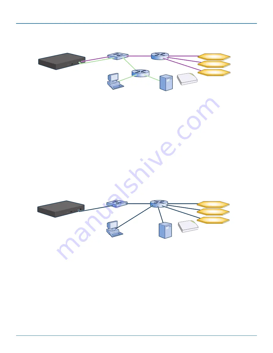
Static Routes: SmartPath EMS VMA sends traffic destined for 10.1.6.0/24 to 10.1.2.1.
SmartPath EMS VMA sends traffic destined for 10.1.7.0/24 to 10.1.2.1.
Default Gateway: 10.1.1.1 (SmartPath EMS VMA sends traffic here when there are no specific routes to a destination.)
Figure 7-2. Using both MGT and LAN interfaces.
NOTE: To set static routes after you log in to the GUI, click Home > Administration > SmartPath EMS VMA Settings > Routing >
Add, set the destination IP address, netmask, and gateway, and then click “Apply.”
When only the MGT interface is enabled, both types of management traffic use it. A possible drawback to this approach is that
you cannot separate the two types of management traffic into two different networks. For example, if you have an existing man-
agement network, you would not be able to use it for SmartPath EMS VMA management traffic. Both SmartPath EMS VMA and
SmartPath AP management traffic would need to flow on the operational network because SmartPath EMS VMA would need to
communicate with the SmartPath APs from its MGT interface (see Figure 7-3). However, if the separation of both types of traffic
is not an issue, then using just the MGT interface is a simple approach to consider.
MGT
10.1.1.8/24
LAN
0.0.0.0/0
Switch
Router
Clusters in different subnets
10.1.3.0/24
10.1.4.0/24
10.1.5.0/24
10.1.1.1
Admin
10.1.7.34
SCP Server
10.1.6.12
SmartPath EMS VMA
Each cluster contains
multiple SmartPath APs.
Each cluster contains
multiple SmartPath APs
Clusters in different subnets
Default Gateway: 10.1.1.1 (SmartPath EMS VMA sends all traffic to the default gateway.)
Figure 7-3. Using just the MGT interface.
8. After you finish configuring the network settings, restart network services by entering 6 (6 Restart Network Services) and then
enter yes to confirm the action. You can now disconnect the serial cable.
Connecting to the GUI through the MGT Interface
1. Connect Ethernet cables from the MGT interface and LAN interface—if you are using it—to the network.
2. Connect an Ethernet cable from your management system to the network so that you can make an HTTPS connection to the
IP address that you set for the MGT interface.


