


CT-600-2
37
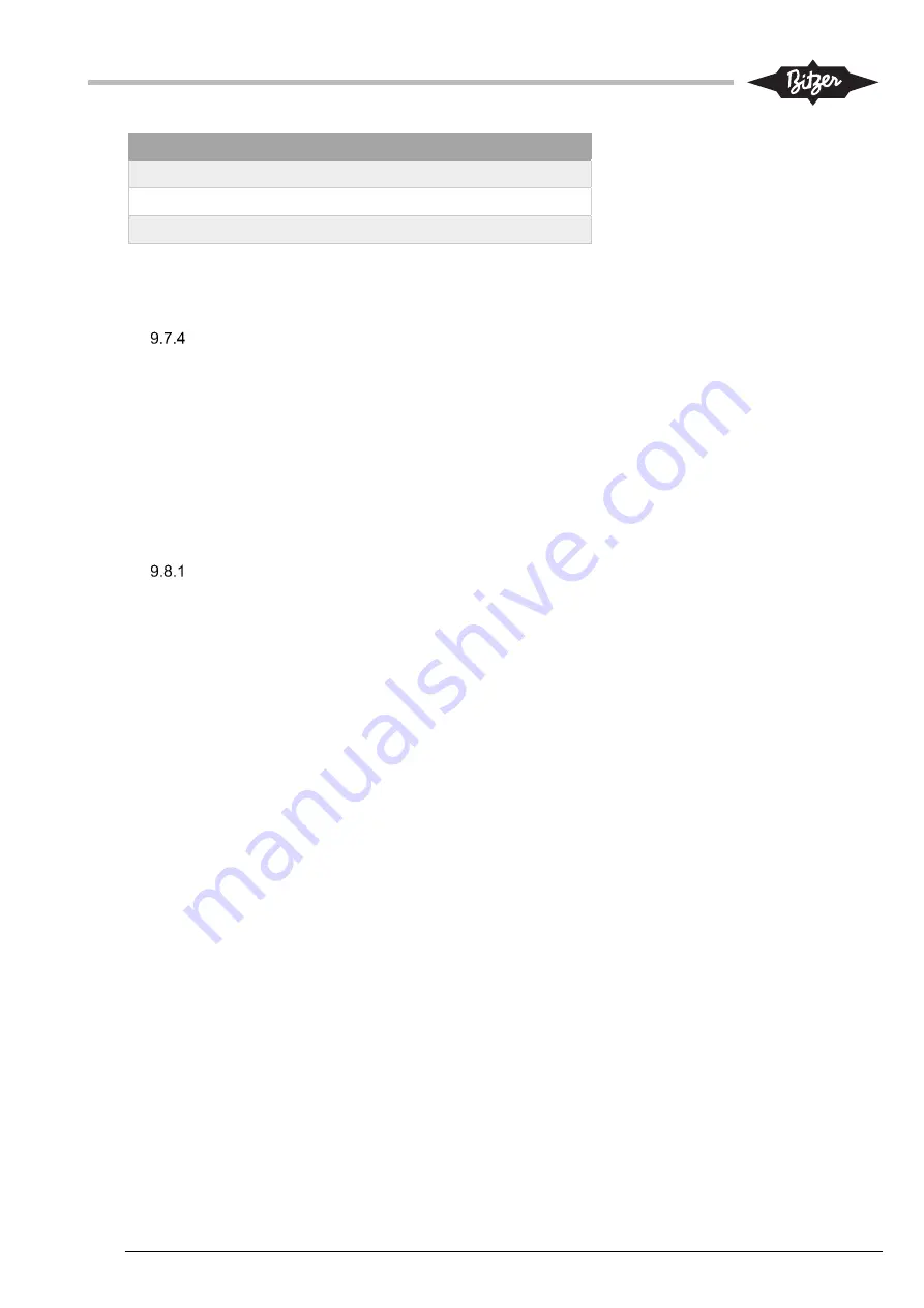
Maximum Speed (Hz)
A
B
50
20.00
0
60
16.67
0
70
14.29
0
For other min/max speed setting, use above formula to find correct factors A and B. Assure to have
corresponding setup on the drive (calibration 0 – 10V must correspond to same speed range).
Current calibration factor in ACP LINK
The current signal is sent to the electrical panel IO-module, typically as a 0-10V signal. The signal must be
calibrated to show the correct value. On WEG CFW11 VSD types the maximum current value can be found in
parameter P0135 “Max. Output Current” and this value can be used to scale the current signal, according to
the formula:
Current signal [A] = Input [0...1000] / Motor current AI calibration factor A. Input “1000” equals 10V.
Example: If parameter 135 shows a value of 468A, then the calibration factor will be: 1000/468 = 2.14.
9.8
Backup and restore of system configuration and settings
ACP LINK panel PLC (M251)
The complete configuration, including the basic setup, parameter and timer values can be stored to and
restored from a file on the PLC. The files can be downloaded or uploaded to an SD-card for further use or
storage.
To save and upload files from the PLC to an SD-card:
1.
It is possible to save three different configuration-and-settings files: User setup #1, #2 and #3:
Param. => Save/Restore => Save User Setup and save to one of three files.
2.
The program to upload files to an SD-card can be delivered by BITZER in a zipped file or as files in
a folders (typical folder name: “sd_card_upload_from_plc_to_sd”).
3.
If zipped, take the zip-file and extract directly onto a formatted SD-card (Fat32). Root folder shall
contain two folders “sys” and “usr”. Alternatively, copy the files in the folder for the software onto
the SD-Card.
4.
Take the SD-card with the program and insert it into the slot on the PLC (this can be done, while
the PLC is in operation).
5.
The SD-LED will be blinking a few seconds. Wait about 30 sec. The SD-LED should stop blinking
and continue to be on.
6.
Take out the SD-card.
7.
The SD-card will contain a new folder called “Rcp” with configuration files that can be stored to a
PC. The configuration files are called User_1.Parameter.rcp for User setup #1 and consequently for
the other two setup files. The files can be opened and edited as text files.


