Installation, Operation and Maintenance Manual
VCIOM-15345-EN Rev. 1
February 2022
13
Installation
Section 2: Installation
2.8
Accumulator (Optional)
2.8.1 Introduction
The Biffi EHO Actuator may be equipped with an accumulator for modulating valve
control or to enable manual operation of the actuator if there is a loss of electrical power.
Accumulators always have the nitrogen pressure drained for shipping.
When using this procedure, refer to the Biffi EHO Actuator General Arrangement drawing
and Hydraulic Schematic for the unit being worked on. Schematics shown in this document
are for illustration purposes only.
!
WARNING
This unit contains high-pressure hydraulic fluid and nitrogen gas. Exercise caution when
performing any type of maintenance. Wear proper safety attire and required personal
protective equipment, including safety glasses.
2.8.2
Accumulator Pre-charge
a.
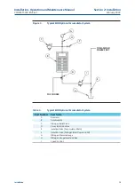
Locate Isolation Valve (25) (Nitrogen Blow Down and Fill) for the Customer
Nitrogen Fill Connection, called out on the General Arrangement Drawing
and Hydraulic Schematic (see Figure 3).
b.
Close the Isolation Valve (25) (Nitrogen Blow Down and Fill) and remove
the pipe plug from the adaptor.
NOTICE
The Adaptor is tapped with a 1/4-NPTF thread.
c.
Ensure 3-way Isolation Valve (22) is turned fully counterclockwise.
d.
Slowly open Isolation Valve (Accumulator drain) (24) and drain all the fluid
back to the reservoir.
e.
Connect a nitrogen supply to the Customer Nitrogen Fill Connection at
Isolation Valve (25) (Nitrogen Blow Down and Fill).
f.
Open the Isolation Valve (25) (Nitrogen Blow Down and Fill) and charge
the Accumulator, to the pre-charge pressure as specified by the Pressure
versus Temperature Graph on the General Arrangement Drawing.


