February 2022
Installation, Operation and Maintenance Manual
VCIOM-15345-EN Rev. 1
72
General Wiring Diagram
Section 11: General Wiring Diagram
Section 11: General Wiring Diagram
11.1
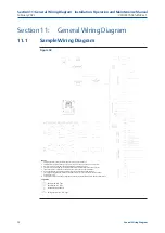
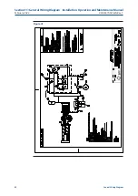
Sample Wiring Diagram
Figure 32
Legends:
Notes:
1.
All digital inputs have an input voltage range of 18-100 V DC or 20-240 V AC.
2.
All digital relay outputs are rated for 5 A @ 30 V DC or 5 A @ 250 V AC Resistive, 2 A Inductive load.
3.
RL1 - RL4 are latching type relays. RL5 is double throw non latching type relay.
4.
Emergency stop requires jumper or normally closed contact (actuator stops when contact is open).
5.
If bare wires (without terminals) are connected, remove a maximum of .25 in. insulation.
6. User replaceable primary fuses (F1 and F2) are located in the Terminal Chamber Enclosure.
7. For single phase supply option, terminal L1 should be used as Live connection and L2 should be used as
neutral connection.
8.
The Shield connections of RS-485, Analog input and Analog ouput lines should be terminated on terminal #24.
Pushbutton N.O. Type
Pushbutton N.C. Type
External Voltage Source
Emergency Switch - N.C. Type


