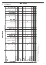
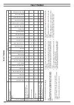
Biasi ADVANCE 15OV Скачать руководство пользователя страница 9

- 9 -

FAULT FINDING

4  FAULT FINDING

FAUL

T FINDING

Components to check

Section of the manual 

(note ref. in brackets)

– (1)

– (2)

– (3)

14.1

– (4)

5

6.5

7

8.4

9.2

10

11.4

12.2

12.2

13.1

– (7)

Appliance lock–out (*)

Defect

Power supply line

Gas supply line

Flue pipes

Cond. drain pipe and trap

C.H. circuit

Condensing heat exchanger

External pump

Fuses (Electronic p.c.b.)

Main electronic p.c.b.

Boiler settings

Control panel electr. p.c.b.

Gas valve

C.H. flow

 temp.

 probe

C.H. return temp. probe

Fan / air restrictor

Ignition electrode

Detection electrode

Safety thermostat

Gas restrictor

Flue temp. probe NTC

Expansion vessel external

Safety valve external

Pressure gauge external

External temp. probe

Room themostat delayed

Display indicates ”Er”

Er 01

 + 

A

B

D

C

Er 02

 + 

C

B

Er 03

 + 

A

Er 04

 + 

B

A

Er 05

 + 

A

Er 06

 + 

A

A

Er 08

 + 

A

Er 09

 + 

A

B

Er 10

 + 

A

B

A

C

B

Er 14

 + 

A

C

B

Er 15

 + 

A

C

B

Er 16

 + 

A

A

Er 17

 + 

A

A

Er 18

 + 

B

D

C

A

L3

B

D

C

A

A

TD

B

B

A

The letter in the cells indicates the possible fault cause.

A

 . . . . .

Z

 indicates the most probably (

A

) to less probably (

 . . . .

Z

)

Содержание ADVANCE 15OV

Страница 1: ...LER ADVANCE 24OV 41 583 37 BOILER Leave this manual adjacent to the gas meter Warning Service repairs must be carried out only by a qualified Gas Safe Registered Engineer who will be responsible for t...

Страница 2: ...ty 21 7 4 Function modes setting modality 21 7 5 Removal of the control panel electronic p c b 21 8 GAS VALVE 22 8 1 Function 22 8 2 Description of the parts 22 8 3 Adjustment 22 8 4 Checks 24 8 5 Rem...

Страница 3: ...rmal fuse Detection electrode C H flow temp probe NTC Safety thermostat Burner Fan Electronic controlbox Gas restrictor Gas valve Pipe silencer Air gas mixer C H return temp probe NTC Ighition electro...

Страница 4: ...om the mains electrici ty supply before removing any covering or compo nent For the most part of the check and maintenance operations it is necessary to remove one or more panels of the case The side...

Страница 5: ...e 2 5 D 4 To access to the parts located behind the control panel to free the hook E and turn it as shown in Figure 2 6 Figure 2 6 E 2 4 Main electronic p c b box Warning isolate the boiler from the m...

Страница 6: ...lock lid F Figure 2 7 7 Free the hooks placed on the three sides indicated and rotate the lid towards left Figure 2 9 Figure 2 9 2 5 Emptying the primary circuit 1 Isolate the cold feed to the F E tan...

Страница 7: ...bu bk bu bn gnye gnye bu bn bu bn brown bu blue bk black wh white rd red gy grey gn green ye yellow vt violet og orange gnye green yellow rdwh red white terminal block Fuse 2AF 250VAC 5x20 wh wh wh w...

Страница 8: ...8 DIAGRAMS 3 2 Circuit voltages Figure 3 2 Electrical voltages with burner on only during C H operation 230 230 Safety thermostat 1 Fan Supply network 230 C H external pump 230 Gas valve...

Страница 9: ...r p c b Gas valve C H flow temp probe C H return temp probe Fan air restrictor Ignition electrode Detection electrode Safety thermostat Gas restrictor Flue temp probe NTC Expansion vessel external Saf...

Страница 10: ...boiler is off FAULT FINDING Lock out is indicated as Er on the display Note Useful information can be obtained also from the optical indication given by the appliance display see section 4 1 1 Check f...

Страница 11: ...RESET Flame detection error Er 69 Wiring error lockout L3 Useful output limitation temperature differ ence between probes higher than 25 C Boiler test performing Td Thermostat Delayed Boiler test per...

Страница 12: ...an on page 27 3 Disconnect the detection electrode connector D the ignition electrodes connector E and the earth wire F 4 Disconnect the fan connector G by pressing the plastic hook placed on the side...

Страница 13: ...e it is deemed necessary to undertake a com bustion analysis as detailed in chapter 8 3 Adjust ment on page 22 section 8 GAS VALVE on page 22 Figure 5 4 Q Caution After any periodical servicing or dis...

Страница 14: ...ies the fan regulating its speed The Main electronic control ignition p c b has a safety function and any incorrect interventions or tampering can result in condi tions of dangerous functioning of the...

Страница 15: ...ontrol panel p c b key If the power requested is lower than 40 of the maximum power output then control is achieved by switching ON the burner at minimum power then switching OFF ON OFF function If th...

Страница 16: ...ves details of each parameter and the pos sible value that can be set Important at the end of the setting operation it is important to fill update the table in the installation manual see chapter COMM...

Страница 17: ...ising rate gradient Pr 31 00 99 0 600 sec factory set 10 60 sec Min useful output C H or D H W Pr 32 00 99 0 100 factory set 00 0 Tab 9 1 6 5 Checks Check that the fuses are complete If the Main elect...

Страница 18: ...p c b 7 It is not necessary to utilise static protections but it is advis able to ensure that the p c b is handled with care and held at the edges and with clean dry hands Attention After installing t...

Страница 19: ...cancels lock Is fan rpm exact YES Is flue temperature higher than 110 C YES NO beginning of wait period End of wait period YES NO YES starts ignition discharges Opens gas valve beginning of ignition p...

Страница 20: ...g er ror flashing number Er 11 RESET Flame detection error Er 12 Faulty central heating temp probe NTC return Er 13 Differential between the flow and return is too close LCD FUNCTION Er 14 RESET Fault...

Страница 21: ...10 C H temperature C calculated by external sensor d4 66 C H flow temperature C d5 78 C H return temperature C d6 44 Flue temperature C d8 67 Fan speed the value has to be x 100 4400 rpm d9 44 Number...

Страница 22: ...isolation switch 6 Set the boiler in C H function as illustrated in Figure 8 3 Figure 8 3 C H function 7 Make sure that the roomthermostat is in the heat request position 8 Read the inlet pressure val...

Страница 23: ...when the display shows the letters cP that alternate with the heating water temperature value e g 60 the chimney sweep function is at maximum output in heating mode Fig ure 8 8 Warning If the boiler...

Страница 24: ...age 5 of this manual 2 Disconnect the connector K Figure 8 12 see also connec tor E Figure 8 2 Figure 8 12 J K L M 3 Turn off the gas supply and disconnect the gas isolation cock connector from the in...

Страница 25: ...y covering or compo nent Disconnect the cable from the Temperature probe Measure the temperature of the pipe D only C H flow temper ature probe where the Temperature probe is located and check the ele...

Страница 26: ...26 TEMPERATURE PROBE Figure 9 4 E F...

Страница 27: ...C D E F A B G H 3 Disconnect the air manifold E Figure 10 2 4 Unscrew the gas connector F and remove the gas pipe G 5 Disconnect the connector C 6 Disconnect the fan connector D by pressing the plast...

Страница 28: ...ectrodes carrying out the removal operation in reverse order Warning A new sealing gasket must be used during refitting of the electrodes on all occasions of re moval 11 3 Removal of the air gas duct...

Страница 29: ...n electrodes see section 11 2 Removal of the Ignition and detection electrodes on page 28 3 Unscrew the screws H Figure 11 1 and remove the cover of the combustion chamber 4 Remove the front insulatio...

Страница 30: ...the boiler from the mains electrici ty supply before removing any covering or compo nent The detection electrode in Figure 11 8 also functions as a sensor for the correct drainage of the condensate S...

Страница 31: ...boiler should maintain a temperature below that of the safety thermostat and no overheat intervention should occur Warning isolate the boiler from the mains electrici ty supply before removing any co...

Страница 32: ...the heat exchanger part shown in Figure 13 3 may be damaged Check that the plastic part of the heat exchanger is not damaged Figure 13 3 13 2 Removal Warning isolate the boiler from the mains electric...

Страница 33: ...E NTC AND SAFETY THERMAL FUSE Figure 13 4 500 1000 1500 2000 2500 3000 3500 4000 4500 5000 5500 6000 6500 7000 7500 8000 8500 9000 9500 10000 10500 11000 11500 12000 12500 20 25 30 35 40 45 50 55 60 6...

Страница 34: ...uire any particular maintenance but just check 1 That no solid deposits have formed if so remove them 2 That the condensate drain piping is not clogged To clean the inside of the siphon remove it and...

Страница 35: ...VANCE 18OV 1 BI1503 109 Fan mod ADVANCE 24OV 1 BI1563 104 4 Gas valve 1 BI1313 103 SIT 848 Sigma 0848135 5 Main Electronic control ignition p c b 1 BI2535 101 6 Control panel electronic p c b 1 BI2445...

Страница 36: ...Biasi UK Ltd Commercial Road Leamore Enterprise Park WALSALL WS2 7NQ Sales Tel 01922 714600 Tech Service Tel 01922 714636 www biasi co uk 1796232450 17962 3245 0 0719 36A4 UK 11 02 2019 N...

Отзывы: