


- 24 -
GAS VALVE
26
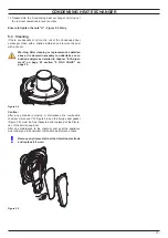
Close the air-flue sampling points.
27
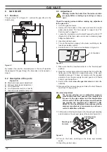
After adjustment fit the protective brass plug ("C" - Figure
8.2).
Important: after the gas pressure checks and any adjust-
ment operations, all of the test points must be sealed and
tested with LDF .
8 .4 Checks
Warning: isolate the boiler from the mains electrici-
ty supply before removing any covering or compo-
nent .
Check the on-off operators coils
1 Remove the front panel of the case.
2 Disconnect the electrical connector "E" (Figure 8.2).
3 Measure the electrical resistance between the connector pins
of the on-off operators as illustrated in Figure 8.11.
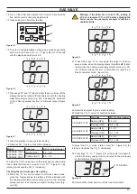
Figure 8 .11
Lower on-off operator
approx. 920 Ω*
Upper on-off operator
approx. 6400 Ω*
*at ambient temperature.
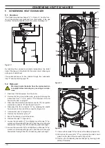
8 .5 Removal of the gas valve
Warning: isolate the boiler from the mains electrici-
ty supply before removing any covering or compo-
nent .
1 Remove the front panel of the case as explained in the sec-
tion "2.3 Control panel" on page 5, of this manual.
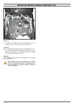
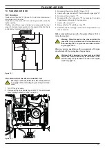
2 Disconnect the connector "K" (Figure 8.12), see also connec-
tor "E" (Figure 8.2).
Figure 8 .12
J
K
L
M
3 Turn off the gas supply and disconnect the gas isolation cock
connector from the inlet port of the gas valve.
4 Unscrew the connector "M" (Figure 8.12) and remove the
pipe "J".
5 Unscrew the screws "L" and remove the valve (Figure 8.12).
6 Reassemble the valve carrying out the removal operations in
reverse order.
Warning: Be careful not to damage the OR gasket of
the gas pipe when inserting the pipe in the air box
(air/gas mixer) .
Before fitting a new valve, it is advisable to preset it as fol
-
lows .
7 Remove the brass plug and turn the plastic screw inside it
fully clockwise until it stops. Do not overtight.
8 Turn it counter-clockwise 2 and 3/4 turns.
9
Adjust the gas valve using the flue analyser as described in
section "8.3 Adjustment" on page 22.
After any service operation on the components of the gas
circuit check all the connections for gas leaks .
Warning: After cleaning or replacement as detailed
above, it is deemed necessary to undertake a com-
bustion analysis as detailed in section "8 .3 Adjust-
ment" on page 22 .
Содержание ADVANCE 15OV
Страница 26: ...26 TEMPERATURE PROBE Figure 9 4 E F...