


- 22 -
GAS VALVE
8 GAS VALVE
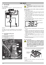
8 .1 Function
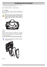
The gas valve "A" in Figure 8.1 controls the gas inflow to the
boiler burner.
Figure 8 .1
A
By means of an electric command given to the on-off operators
the passage of the gas through the Gas valve can be opened or
closed.
8 .2 Description of the parts
(Figure 8 .2)
B
Maximum boiler power adjustment
C
Minimum boiler power adjustment
D
On-off operators
E
On-off operators electric connector
F
Gas valve inlet pressure test point
Figure 8 .2
F
E
D
B
C
8 .3 Adjustment
Warning: isolate the boiler from the mains electrici-
ty supply before removing any covering or compo-
nent .
Check the supply pressure before making any adjustment
to the gas valve .
1 Close the gas inlet valve.
2 Remove the front panel of the case and lower the control
panel (see sections "2.2 Case panels" on page 4 and "2.3
Control panel" on page 5).
3 Loosen the internal screw on the Inlet Pressure Test Point "F"
(Figure 8.2) of the Gas valve and connect a pressure gauge
using a suitable hose.
4 Open the gas inlet valve.
5 Turn on the electricity supply to the boiler, switching on the
fused spur isolation switch.
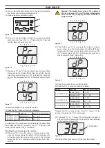
6 Set the boiler in C.H. function as illustrated in Figure 8.3.
Figure 8 .3
C.H. function
7 Make sure that the roomthermostat is in the “heat request”
position.
8 Read the inlet pressure value and ensure that it is within the
limits given in the table
Gas supply pressures
, of the user/
installation manual. If it does not comply with the required
pressure check the gas supply line and governor for faults
and/or correct adjustment.
9 Switch off the boiler
close the gas inlet valve
and close the
water tap.
10 Disconnect the pressure gauge and close the Inlet Pressure
Test Point "F" (Figure 8.2).
Gas valve adjustment
The person carrying out a combustion measure-
ment should have been assessed as competent in
the use of a flue gas analyser and the interpretation
of the results. The flue gas analyser used should be
one meeting the requirements of BS7927 or BS-
EN50379-3 and be calibrated in accordance with the
analyser manufacturers’ requirements, and have a
current calibration certificate.
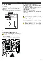
11
Fit the probe of the flue analyser in the flue exhaust sampling
point located on the exhaust pipes of the boiler (Figure 8.4).
Figure 8 .4
Sampling points
Flue exhaust
Sampling points
Air intake
12 Turn on the boiler, switching on the fused spur isolation
switch.
13 Open the gas inlet valve.
Содержание ADVANCE 15OV
Страница 26: ...26 TEMPERATURE PROBE Figure 9 4 E F...