


- 20 -
CONTROL PANEL ELECTRONIC P.C.B.
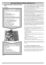
7 CONTROL PANEL ELECTRONIC P .C .B .
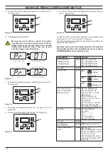
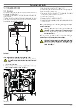
7 .1 Function
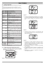
Figure 7 .1
A
D
B
C
A
C.H. temperature increase key
B
C.H. temperature reduce key
C
Reset/Stand-by/Winter/Summer key
D
Display
The Control panel electronic p.c.b. can give to the service 3 lev-
els of informations:
• Normally information
• Info modality
• Function modes setting modality
7 .2 Normally information
KEY
RESET
The symbol indicates that the boiler can be di-
rectly reactivated by the user, by pressing the
reset button.
The symbol indicates that the fault requires in-
tervention on behalf of specialised technical as-
sistance.
All symbols represented with lines that surround
them, indicate that the symbol is flashing.
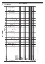
SIGNAL DISPLAYED BY THE LCD
LCD
FUNCTION
Er 01 + RESET
Lack of burner ignition on safety lockout
Er 02 + RESET
Safety thermostat intervention lockout
Er 03 + RESET
General lockout
Er 04 +
Faulty primary circuit (no water or ab-
sence of flow)
Er 05 +
Faulty fan control system
Er 06 +
Faulty C.H. temp. probe NTC
Er 08 +
Faulty external temp. probe NTC
Er 09 +
Faulty flue temp. probe NTC
Er 10 + RESET
Flue probe intervention lockout
Flame detection error (An fl er
-
ror flashing number)
Er 11 + RESET
Flame detection error
Er 12 +
Faulty central heating temp. probe NTC
(return)
Er 13 +
Differential between the flow and return
is too close
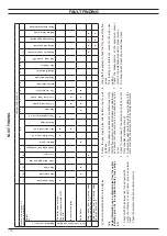
LCD
FUNCTION
Er 14 + RESET
Faulty pump or primary temperature
above 105° C
Er 15 + RESET
None or too low water flow; Faulty pump
(temp. difference between probes higher
than 35° C)
Er 16 + RESET
Possible exchange of NTC probes (Flow
or Return) or pump wrongly mounted
(upside – down)
Er 17 + RESET
Faulty c.h. temp. probe NTC (Flow or
Return)
Er 18 + RESET
Faulty primary circuit (no water or ab-
sence of flow)
Er 25 + RESET
Flame detection error
Er 69
Wiring error lockout
Boiler Stand-By, hyphens are turned on
in sequence to simulate running /anti-
freeze protection activated)
Boiler waiting for heat request
Boiler in winter mode
The primary circuit temperature is dis-
played.
Boiler on demand for C.H. power.
Burner ignition (spark)
Flame present (Burner on)
Boiler in anti---freeze phase (
bP
flashing
+ temperature flashing)
Boiler in antifrost phase (
AF
flashing +
temperature flashing)
Set C.H. (all other symbols are disabled)
Remote control connected (one flash
every 4 sec.)
Pump activated for the post---circulation
phase (
Po
fl temperature flash
-
ing)
Delayed burner ignition for setting the
system (
uu
fl temperature flash
-
ing)
Maintenance required
The wrench symbol is flashing (without
showing any error)
Содержание ADVANCE 15OV
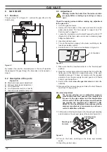
Страница 26: ...26 TEMPERATURE PROBE Figure 9 4 E F...