


- 15 -
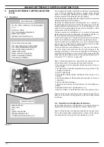
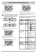
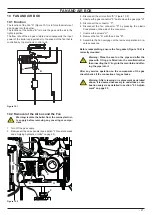
MAIN ELECTRONIC CONTROL/IGNITION P.C.B.
Figure 6 .2
1 2
3
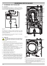
5
6
4
7
8
9
10
11
12
13
1
Connector - ignition electrode.
2
Connector - flame detection electrode
3
Connector - controller fan
4
Connector - C.H. return temperature probe NTC
5
Connector - flue temperature probe NTC
6
Connector - external temperature probe (optional)
7
Connector - safety thermostat and C.H. flow temperature
probe NTC
8
Connector - remote control (optional)
9
Connector - display and function control / C.H. temperature
adjustment control panel p.c.b.
10
Fuse F1, F2 2A F
11
Connector - electric supply Main electronic control/ignition
p.c.b.
12
Connector - electric supply control panel p.c.b.
13
Connector - gas valve, external pump and fan
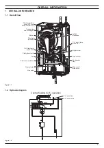
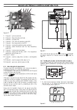
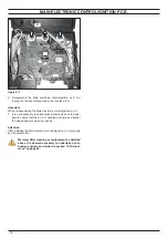
6 .3 Checking the temperature
The
Main electronic control/ignition p.c.b.
makes it possible to
separately adjust the C.H. water flow temperature.
The temperature of the water is converted into an electric signal
by means of temperature probes.
The user, setting the desired temperature with the control panel
p.c.b. key
.
If the power requested is lower than 40% of the maximum power
output then control is achieved by switching ON the burner at
minimum power, then switching OFF (ON/OFF function). If the
power requested is higher, then the burner is switched ON at
maximum power and will control by modulating to 40% of the
maximum power output.
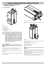
During the C.H. operation (Figure 6.3), the signal coming from
the C.H. temperature probe is compared to the signal given by
the control panel through the adjustment made by the user (key
). The result of such a comparison operates the fan
speed thus regulating the gas flow rate and consequently chang
-
ing the useful output of the boiler.
Figure 6 .3
The control sequences in function
in function are illustrated
in detail in sections "6.7 Thermal control in the
mode" on
page 19.
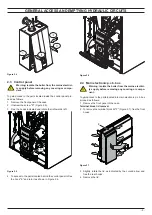
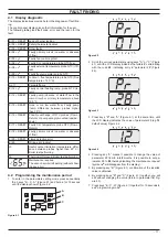
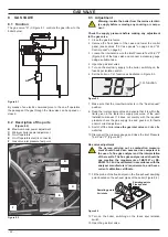
6 .4 Setting the boiler control function modes
It is possible to select the various boiler control function modes
hereafter named “parameters” by using the keys of the control
panel p.c.b.
Figure 6 .4
A
B
C
1 To enter in the parameters setting mode press sequentially
the 3 keys "B - C - A" (Figure 6.4) and hold in for 10 second
until the display shows Figure 6.5.
Figure 6 .5
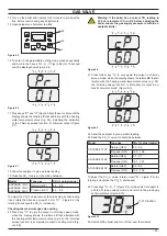
Содержание ADVANCE 15OV
Страница 26: ...26 TEMPERATURE PROBE Figure 9 4 E F...