


- 21 -
CONTROL PANEL ELECTRONIC P.C.B.
LCD
FUNCTION
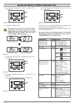
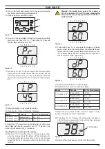
Boiler in chimney sweep in function.
The activation of the chimney sweep oc-
curs configuring the "parameter P09=01"
and is visualized:
LP = minimum D.H.W.
hP = minimum heating
cP = maximum heating
dP = maximum D.H.W..
The transition occurs with keys A (in-
crease) and B (decrease) C.H. tempera-
ture.
The writing on the display alternates.
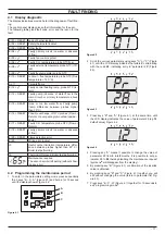
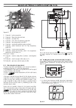
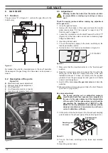
7 .3 Info modality
The INFO mode allows the display of some information on the
boiler functioning status. In case of malfunctioning of the boiler,
it may be useful to communicate such information to the Author-
ised Service Centre Engineer so that the causes can be under-
stood.
In order to access the INFO mode, press keys A and C (Figure
7.1) at the same time until the letter di appears on the display that
alternates with a code (Figure 7.1).
Figure 7 .2
To scroll the values press B (reduce) and A (increase). keys (Fig-
ure 7.1). In order to exit the INFO mode, hold keys A and C (Fig-
ure 7.1) pressed at the same time. The following table gives de-
tails of each parameter and the possible value that can be show.
Description
Parameter
Value
External temperature °C (if fitted)
d1
-5
K value (external probe diagram)
(the value is x 10)
d2
12
Offset
(Translation of K diagram ± 15°C)
d3
-10
C.H. temperature °C
(calculated by external sensor)
d4
66
C.H. flow temperature °C
d5
78
C.H. return temperature °C
d6
44
Flue temperature °C
d8
67
Fan speed (the value has to be x
100 = 4400 rpm)
d9
44
Number of months to maintenance
c3
12
SW version BC (burner control)
dc
01
SW version MB (main board)
dd
03
Tab. 10.1
7 .4 Function modes setting modality
It is possible to select the various boiler control function modes
hereafter named “parameters” by using the keys of the control
panel p.c.b.
During the function modes setting, the boiler does not operate.
To get in function modes setting modality see section "6.4 Setting
the boiler control function modes" on page 15.
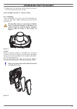
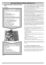
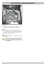
7 .5 Removal of the control panel electronic
p .c .b
Warning: isolate the boiler from the mains electrici-
ty supply before removing any covering or compo-
nent .
1 Remove all the body panels (see section "2.2 Case panels"
on page 4).
2 Gain access to the parts located inside the
Control panel
electronic p.c.b.
as explained in the section "2.3 Control pan-
el" on page 5 of this manual.
3 Remove all the wiring "E" connected to the
Control panel
electronic p.c.b.
(Figure 7.3).
Figure 7 .3
E
F
G
I
F
E
4 Unscrew the screws "F".
5
Delicately flex the hooks "G" in the directions indicated (Fig
-
ure 7.3) in order to release the circuit from the box.
6 Remove the
Control panel electronic p.c.b.
7 Reassemble the
Control panel electronic p.c.b.
carrying out
the removal operations in the reverse order.
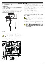
Содержание ADVANCE 15OV
Страница 26: ...26 TEMPERATURE PROBE Figure 9 4 E F...