


- 17 -
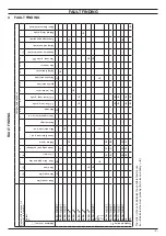
MAIN ELECTRONIC CONTROL/IGNITION P.C.B.
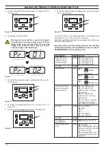
PARAMETER
DIGIT VALUES
Chimney sweep
function
Pr 09 00 =
No chimney sweep fun
(
factory set
)
01 =
D.H.W. low power
sweep---test
02 =
C.H. low power sweep-
--test
03 =
C.H. max power
sweep---test
04 =
D.H.W. max power
sweep---test
C.H. reignition
frequency
Pr 10 00÷99
(0÷600 sec.)
(factory set
30 =
3 minutes)
C.H. pump post-
circulation
Pr 11 00÷99
(0÷600 sec.)
(factory set
10 =
1 minute)
Max. useful output in
C.H. mode
Pr 12 00÷99
(0÷100%)
C.H. pump working type
Pr 13 00 =
Depends on room
thermostat (
factory set
)
04 =
Always running
Ignition power
Pr 14 00÷99
(0÷100%)
factory set:
Natural gas (G20)
70 =
ADVANCE 15OV
51 =
ADVANCE 18OV
58 =
ADVANCE 24OV
Propane (G31)
70 =
ADVANCE 15OV
51 =
ADVANCE 18OV
58 =
ADVANCE 24OV
K value (external probe
diagram)
Pr 15 01
(=0,1) ÷
60
(=6,0)
K value factory set:
00 =
OFF
Min. re-ignition power
Pr 16 00
÷
99
(0%÷100 %)
(factory set
00
= 0%)
Not used
Pr 17
NTC on the C.H. return
Pr 18 00 =
Probe not present
01 =
Probe present
(
factory set
)
LCD type
Pr 19 00 =
TOP
02 =
MEDIUM
(factory set)
Not used
Pr 20
Not used
Pr 21
Not used
Pr 22
Not used
Pr 23
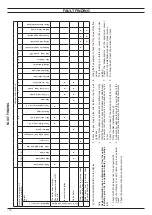
Duty Cycle Zone,
Only if Pr 04 = 01 or
02 and contemporary
requests from Z1 and
Z2
Pr 24 10÷30
(0÷30 min.)
(factory set 30 = 30 minute)
C.H. flow temperature
in antifreeze protection
mode °C
Pr 25 25÷85
(factory set 45 °C)
Not used
Pr 26
C.H. minimum setpoint
Pr 27 25÷45
(factory set 25 °C)
Maintenance intervals
Pr 28 00
÷
48
(= months)
(
factory set
12
months)
Presence of domestic
cold water temp.
probe or set of inlet cold
water with solar control
Pr 29 00
= No NTC probe (
factory
set
)
01
= Yes NTC probe
04
÷
45
(°C) temp.
NTC inlet probe with solar
control
PARAMETER
DIGIT VALUES
Not used
Pr 30
C.H. temperature rising
rate (gradient).
Pr 31 00÷99
(0÷600 sec.)
(factory set
10 =
60 sec.)
Min. useful output C.H.
or D.H.W.
Pr 32 00÷99
(0%÷100%)
(factory set
00 =
0%)
Tab 9.1
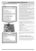
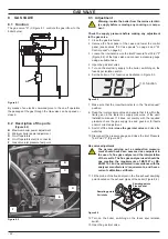
6 .5 Checks
Check that the fuses are complete
If the Main electronic control/ignition p.c.b. does not supply any
device (external pump, fan, etc.) check that the fuses 10 (Figure
6.2) are complete.
If a fuse has blown replace it with one that has the same charac-
teristics after having identified the reason for failure.
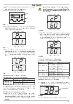
Lock sequence
Start the boiler until the burner is ignited.
With the burner firing, interrupt the gas supply. The Main elec
-
tronic control/ignition p.c.b. must carry out four complete ignition
cycles and then, after about 4 minutes, goes to lock-out state.
Switch off and on the electricity supply to the boiler, by means of
the fused spur isolation switch, the device must not unlock and
the burner must not turn on.
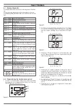
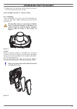
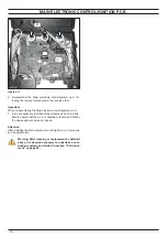
6 .6 Removal of the electronic control p .c .b
Warning: isolate the boiler from the mains electrici-
ty supply before removing any covering or compo-
nent .
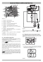
When replacing the Main electronic control/ignition p .c .b .
all parameters must be correctly checked / adjusted accord-
ingly with the values noted in table in the installation manual
see chapter COMMISSIONING section: Setting record (for
information on parameters see also section "6 .4 Setting the
boiler control function modes" on page 15) .
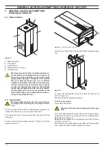
1 Remove all the body panels (see section "2.2 Case panels"
on page 4).
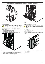
2 Gain access to the parts located inside the Main electronic
p.c.b. box as explained in the section "2.4 Main electronic
p.c.b. box" on page 5 of this manual.
3 Remove all the wiring connected to the
Main electronic con-
trol/ignition p.c.b
.
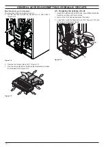
4
Delicately flex the hooks "D" in the directions indicated (Fig
-
ure 6.11) in order to release the circuit from the box.
5 Remove the
Main electronic control/ignition p.c.b
.
Содержание ADVANCE 15OV
Страница 26: ...26 TEMPERATURE PROBE Figure 9 4 E F...