


5
3
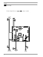
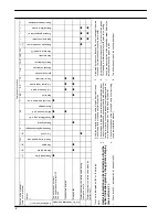
Diagrams
3.1
Wiring diagram
1
2
3
L
N
1
3
4
t
M
~
t
Room thermostat
Pump
terminal block
Electric supply
terminal block
Gas valve
External temp.
Remote
Fan
Ignition
electrodes
Flame detection
electrode
Time switch (option)
Flue temp.
Safety
thermostat
C.h. flow temp.
probe NTC
probe
Condensate
trap
bu
bn
bu
bn
og
vt
bu
bn
bk
bk
rd
rd
bu
gnye
bn
ye
vt
bn = brown
bu = blue
bk = black
wh = white
rd = red
og
gy = grey
gn = green
ye = yellow
vt = violet
og = orange
gnye = green/yellow
rdwh = red/white
ye
bk
bk
bk
bk
bk
bk
bu
bu
bu
bu
rd
rd
bk
bk
gy
gy
gy
gy
bk
bu
rd
rd
bu
bk
bu
bn
gnye
gnye
bu
bn
bu
gy
terminal block
probe NTC
Fuse 2AF 250VAC
5x20
wh
wh
wh
wh
wh
wh
gy
wh
og
og
bk
bk
wh
wh
t
wh
wh
C.h. return temp.
probe NTC
gnye
Содержание Activ A 12OV
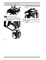
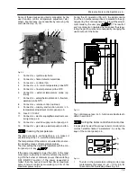
Страница 28: ...Temperature probe 26 D F B Fig 9 4...