


27
10
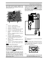
Fan and Air box
10.1
Function
The function of the Fan
A
(Fig. 10.1) is to force the mix-
ture of air and gas into the burner.
The function of the Air box
B
is to mix the gas and the
air in the right proportion.
The flow rate of the air---gas mixture and consequently
the input power of the boiler is proportional to the speed
of the fan that is controlled by the electronic control
p.c.b.
A
B
Fig. 10.1
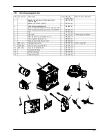
10.2
Removal of the Fan and the Air box
Warning: isolate the boiler from the mains
electricity supply before removing any
covering or component.
1
Turn off the gas supply.
2
Remove all the case panels (see section 2).
D
G
C
Fan gasket
E
F
A
D
H
Fig. 10.2
3
Disconnect the rubber pipe
C
(Fig. 10.2).
4
Unscrew the gas connectors
D
and remove the
gas pipe
E
.
5
Disconnect the connector
F
6
Disconnect the fan connector
G
by pressing the
plastic hook placed on the side of the connector.
7
Unscrew the screws
H
.
8
Remove the fan
A
with the air box
B
.
9
Remove the screws
I
and the air box
B
(Fig. 10.3).
I
B
I
I
Fig. 10.3
10
Open the strip
J
by sliding the edges with the help
of a screwdriver and remove the Air box
Fig. 10.4.
J
B
Fig. 10.4
11
Assemble the Fan and the Air box carrying out
the removal operations in reverse sequence.
Before reassembling ensure the fan gasket
(Fig. 10.2) is correctly mounted.
After any service operation on the components of
the gas circuit check all the connections for gas
leaks.
Warning: After cleaning or replacement as
detailed above, it is deemed necessary to
undertake a combustion analysis as detailed
in chapter 8.3 section 11.
Содержание Activ A 12OV
Страница 28: ...Temperature probe 26 D F B Fig 9 4...